4 x86 Assembly and C
In this chapter, we will explore assembly language, and how it connects to C. But why should we do so? Isn’t it better to trust the compiler, plus no one writes assembly anymore?
Not quite. Surely, the compiler at its current state of the art is
trustworthy, and we do not need to write code in assembly, most of
the time. A compiler can generate code, but as mentioned
previously, a high-level language is a collection of patterns of a
lower-level language. It does not cover everything that a hardware
platform provides. As a consequence, not every assembly instruction can
be generated by a compiler, so we still need to write assembly code for
these circumstances to access hardware-specific features. Since
hardware-specific features require writing assembly code, debugging
requires reading it. We might spend even more time reading than writing.
Working with low-level code that interacts directly with hardware,
assembly code is unavoidable. Also, understanding how a compiler
generates assembly code could improve a programmer’s productivity. For
example, if a job or school assignment requires us to write assembly
code, we can simply write it in C, then let gcc do the hard
work of writing the assembly code for us. We merely collect the
generated assembly code, modify as needed and be done with the
assignment.
We will learn objdump extensively, along with how to use
Intel documents to aid in understanding x86 assembly code.
4.1 objdump
objdump is a program that displays information about
object files. It will be handy later to debug incorrect layout from
manual linking. Now, we use objdump to examine how high
level source code maps to assembly code. For now, we ignore the output
and learn how to use the command first. Suppose that we have an
executable binary named hello compiled from a
hello.c that prints “Hello World”. It is simple to use
objdump:
$ objdump -d hello-d option only displays assembled contents of executable
sections. A section is a block of memory that contains either
program code or data. A code section is executable by the CPU, while a
data section is not executable. Non-executable sections, such as
.data and .bss (for storing program data),
debug sections, etc, are not displayed. We will learn more about
sections when studying the ELF binary file format in chapter 5, The
Anatomy of a Program. On the other hand:
$ objdump -D hellowhere -D option displays assembly contents of all
sections. If -D, -d is implicitly assumed.
objdump is mostly used for inspecting assembly code, so
-d is the most useful and thus is set by default.
The output overruns the terminal screen. To make it easy for reading,
send all the output to less:
$ objdump -d hello | lessTo intermix source code and assembly, the binary must be compiled
with -g option to include source code in it, then add
-S option:
$ objdump -S hello | lessThe default syntax used by objdump is AT&T syntax.
To change it to the familiar Intel syntax:
$ objdump -M intel -D hello | lessWhen using -M option, option -D or
-d must be explicitly supplied. Next, we will use
objdump to examine how compiled C data and code are
represented in machine code.
Finally, we will write a 32-bit kernel, therefore we will need to compile a 32-bit binary and examine it in 32-bit mode:
$ objdump -M i386,intel -D hello | less-M i386 tells objdump to display assembly content using
32-bit layout. Knowing the difference between 32-bit and 64-bit is
crucial for writing kernel code. We will examine this matter later on
when writing our kernel.
4.2 Reading the output
To have something to read, we compile the hello.c of
chapter 0 once as a 64-bit program, the native format of the machine.
This is the only 64-bit program in the book; every program from the next
section on is compiled with -m32. The flags are the ones of
chapter 0, Setting up the development environment, minus
-m32:
$ gcc -no-pie -fno-pie -fno-asynchronous-unwind-tables -fcf-protection=none -O0 hello.c -o hello
$ objdump -M intel -D hello | less
At the start of the output displays the file format of the object file:
hello: file format elf64-x86-64After the line is a series of disassembled sections:
Disassembly of section .note.gnu.property:
...
Disassembly of section .note.gnu.build-id:
...
Disassembly of section .interp:
...
...
etc
Finally, each disassembled section displays its actual content - which is a sequence of assembly instructions - with the following format:
401126: 55 push rbpThe first column is the address of an assembly instruction. In the above example, the address is
0x401126.The second column is the assembly instruction in raw hex values. In the above example, the value is
0x55.The third column is the assembly instruction. Depending on the section, the assembly instruction might be meaningful or meaningless. For example, if the assembly instructions are in a
.textsection, then the assembly instructions are actual program code. On the other hand, if the assembly instructions are displayed in a.datasection, then we can safely ignore the displayed instructions. The reason is thatobjdumpdoesn’t know which hex values are code and which are data, so it blindly translates every hex value into assembly instructions. In the above example, the assembly instruction ispush rbp.The optional fourth column is a comment - appears when there is a reference to an address - to inform where the address originates. For example, the comment after the
#sign in this line of the.initsection:401004: 48 8b 05 d5 2f 00 00 mov rax,QWORD PTR [rip+0x2fd5] # 403fe0 <__gmon_start__@Base>is to inform that the referenced address from
[rip+0x2fd5]is0x403fe0, where the variable__gmon_start__resides.
In a disassembled section, it may also contain labels. A
label is a name given to an assembly instruction. The label denotes the
purpose of an assembly block to a human reader, to make it easier to
understand. For example, .text section carries many of such
labels to denote where code in a program starts; .text
section below carries two functions: _start and
deregister_tm_clones. The _start function
starts at address 401040, which is annotated to the left of
the function name. Right below the _start label is also the
instruction at address 401040. This whole thing means that
a label is simply a name of a memory address. The function
deregister_tm_clones also shares the same format as every
function in the section.
0000000000401040 <_start>:
  401040:   31 ed                   xor    ebp,ebp
  401042:   49 89 d1                mov    r9,rdx
  401045:   5e                      pop    rsi
...more assembly code....
0000000000401080 <deregister_tm_clones>:
  401080:   b8 18 40 40 00          mov    eax,0x404018
  401085:   48 3d 18 40 40 00       cmp    rax,0x404018
  40108b:   74 13                   je     4010a0 <deregister_tm_clones+0x20>
...more assembly code....
4.3 Intel manuals
The best way to understand and use assembly language properly is to understand precisely the underlying computer architecture and what each machine instruction does. To do so, the most reliable source is to refer to documents provided by vendors. After all, hardware vendors are the ones who made their machines. To understand Intel’s instruction set, we need the document “Intel 64 and IA-32 architectures software developer’s manual combined volumes 2A, 2B, 2C, and 2D: Instruction set reference, A-Z”. The document can be retrieved here: https://software.intel.com/en-us/articles/intel-sdm.
Chapter 1 provides brief information about the manual, and the comment notations used in the book.
Chapter 2 provides an in-depth explanation of the anatomy of an assembly instruction, which we will investigate in the next section.
Chapter 3 - 5 provide the details of every instruction of the x86_64 architecture.
Chapter 6 provides information about safer mode extensions. We won’t need to use this chapter.
The first volume “Intel 64 and IA-32 Architectures Software Developer’s Manual Volume 1: Basic Architecture” describes the basic architecture and programming environment of Intel processors. In the book, Chapter 5 gives the summary of all Intel instructions, by listing instructions into different categories. We only need to learn general-purpose instructions listed in chapter 5.1 for our OS. Chapter 7 describes the purpose of each category. Gradually, we will learn all of these instructions.
Exercise 4.1. Read section 1.3, “Notational Conventions”, in chapter 1 of volume 2, excluding sections 1.3.5 and 1.3.7. Section numbers move from one revision of the manual to the next; if 1.3 is not the section with that title in your copy, find the title in the table of contents.
4.4 Experiment with assembly code
The subsequent sections examine the anatomy of an assembly
instruction. To fully understand, it is necessary to write code and see
the code in its actual form displayed as hex numbers. For this purpose,
we use nasm assembler to write a few lines of assembly code
and see the generated code.
Example 4.1. Suppose we want to see the machine code generated for this instruction:
jmp eaxThen, we use an editor e.g. Emacs, then create a new file, write the
code and save it in a file, e.g. test.asm. Then, in the
terminal, run the command:
$ nasm -f bin test.asm -o test-f option specifies the file format, e.g. ELF, of the
final output file. But in this case, the format is bin,
which means this file is just a flat binary output without any extra
information. That is, the written assembly code is translated to machine
code as is, without the overhead of the metadata from a file format like
ELF. Indeed, after compiling, we can examine the output using this
command:
$ hd testhd (short for hexdump) is a program that displays the
content of a file in hex format. And get the following output:
00000000  66 ff e0                                          |f..|
00000003
The file only consists of 3 bytes: 66 ff e0, which is
equivalent to the instruction jmp eax.
Example 4.2. If we were to use elf as
file format:
$ nasm -f elf test.asm -o testIt would be more challenging to learn and understand assembly instructions with all the added noise1:
00000000  7f 45 4c 46 01 01 01 00  00 00 00 00 00 00 00 00  |.ELF............|
00000010  01 00 03 00 01 00 00 00  00 00 00 00 00 00 00 00  |................|
00000020  40 00 00 00 00 00 00 00  34 00 00 00 00 00 28 00  |@.......4.....(.|
00000030  05 00 02 00 00 00 00 00  00 00 00 00 00 00 00 00  |................|
00000040  00 00 00 00 00 00 00 00  00 00 00 00 00 00 00 00  |................|
*
00000060  00 00 00 00 00 00 00 00  01 00 00 00 01 00 00 00  |................|
00000070  06 00 00 00 00 00 00 00  10 01 00 00 02 00 00 00  |................|
00000080  00 00 00 00 00 00 00 00  10 00 00 00 00 00 00 00  |................|
00000090  07 00 00 00 03 00 00 00  00 00 00 00 00 00 00 00  |................|
000000a0  20 01 00 00 21 00 00 00  00 00 00 00 00 00 00 00  | ...!...........|
000000b0  01 00 00 00 00 00 00 00  11 00 00 00 02 00 00 00  |................|
000000c0  00 00 00 00 00 00 00 00  50 01 00 00 30 00 00 00  |........P...0...|
000000d0  04 00 00 00 03 00 00 00  04 00 00 00 10 00 00 00  |................|
000000e0  19 00 00 00 03 00 00 00  00 00 00 00 00 00 00 00  |................|
000000f0  80 01 00 00 0a 00 00 00  00 00 00 00 00 00 00 00  |................|
00000100  01 00 00 00 00 00 00 00  00 00 00 00 00 00 00 00  |................|
00000110  ff e0 00 00 00 00 00 00  00 00 00 00 00 00 00 00  |................|
00000120  00 2e 74 65 78 74 00 2e  73 68 73 74 72 74 61 62  |..text..shstrtab|
00000130  00 2e 73 79 6d 74 61 62  00 2e 73 74 72 74 61 62  |..symtab..strtab|
00000140  00 00 00 00 00 00 00 00  00 00 00 00 00 00 00 00  |................|
*
00000160  01 00 00 00 00 00 00 00  00 00 00 00 04 00 f1 ff  |................|
00000170  00 00 00 00 00 00 00 00  00 00 00 00 03 00 01 00  |................|
00000180  00 74 65 73 74 2e 61 73  6d 00 00 00 00 00 00 00  |.test.asm.......|
00000190
Thus, it is better just to use flat binary format in this case, to experiment instruction by instruction.
With such a simple workflow, we are ready to investigate the structure of every assembly instruction.
Note: Using the bin format puts nasm by
default into 16-bit mode. To enable 32-bit code to be generated, we must
add this line at the beginning of a nasm source file:
bits 32The examples in this chapter deliberately leave this line out, so that the prefixes which switch a single instruction to 32-bit operands or 32-bit addresses show up in the generated bytes.
4.5 Anatomy of an Assembly Instruction
Chapter 2 of the instruction reference manual provides an in-depth view of instruction format. But, the information is too much that it can overwhelm beginners. This section provides an easier introduction before reading the actual chapter in the manual.
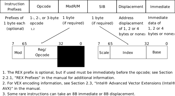
Recall that an assembly instruction is simply a fixed-size series of bits. The length of an instruction varies and depends on how complicated an instruction is. What every instruction shares is a common format described in the figure above that divides the bits of an instruction into smaller parts that encode different types of information. These parts are:
Instruction Prefixes-
appears at the beginning of an instruction. Prefixes are optional. A programmer can choose to use a prefix or not because in practice, a so-called prefix is just another assembly instruction to be inserted before another assembly instruction that such prefix is applicable. Instructions with 2 or 3-byte opcodes include the prefixes by default.
Opcode-
is a unique number that identifies an instruction. Each opcode is given a mnemonic name that is human readable, e.g. one of the opcodes for instruction
addis04. When a CPU sees the number04in its instruction cache, it sees instructionaddand executes accordingly. Opcode can be 1, 2 or 3 bytes long and includes an additional 3-bit field in theModR/Mbyte when needed.
::: {.example} Example 4.3. This instruction:
jmp [0x1234]generates the machine code:
ff 26 34 12The very first byte, ff, is the opcode,
which is unique to jmp instruction. :::
ModR/M-
specifies operands of an instruction. Operand can either be a register, a memory location or an immediate value. This component of an instruction consists of 3 smaller parts:
modfield, or modifier field, is combined withr/mfield for a total of 5 bits of information to encode 32 possible values: 8 registers and 24 addressing modes.reg/opcodefield encodes either a register operand, or extends theOpcodefield with 3 more bits.r/mfield encodes either a register operand or can be combined withmodfield to encode an addressing mode.
The 16-bit and 32-bit tables below list all possible 256 values
of ModR/M byte and how each value maps to an addressing
mode and a register, in 16-bit and 32-bit modes. They are copies of
tables 2-1 and 2-2 in volume 2.
AL AX EAX MM0 XMM0 0 000 Mod 00 |
CL CX ECX MM1 XMM1 1 001 R/M 000
001 010 011 100
101 110 111 000
001 010 011 100
101 110 111 000
001 010 011 100
101 110 111 000
001 010 011 100
101 110 111 |
DL DX EDX MM2 XMM2 2 010 | BL BX EBX MM3 XMM3 3 011 | AH SP ESP MM4 XMM4 4 100 | CH BP1 EBP MM5 XMM5 5 101 | DH SI ESI MM6 XMM6 6 110 | BH DI EDI MM7 XMM7 7 111 |
AL AX EAX MM0 XMM0 0 000 Mod 00 |
CL CX ECX MM1 XMM1 1 001 R/M 000
001 010 011 100
101 110 111 000
001 010 011 100
101 110 111 000
001 010 011 100
101 110 111 000
001 010 011 100
101 110 111 |
DL DX EDX MM2 XMM2 2 010 | BL BX EBX MM3 XMM3 3 011 | AH SP ESP MM4 XMM4 4 100 | CH BP EBP MM5 XMM5 5 101 | DH SI ESI MM6 XMM6 6 110 | BH DI EDI MM7 XMM7 7 111 |
How to read the table: in an instruction, next to the opcode is a
ModR/M byte. Then, look up the byte value in this table to
get the corresponding operands in the row and column.
Example 4.4. An instruction uses this addressing mode:
jmp [0x1234]Then, the machine code is:
ff 26 34 120xff is the opcode. Next to it,
26 is the ModR/M byte. Look
up in the 16-bit table2, the first operand is in the row,
equivalent to a disp16, which means a 16-bit offset. Since
the instruction does not have a second operand, the column can be
ignored.
Example 4.5. An instruction uses this addressing mode:
add eax, ecxThen the machine code is:
66 01 c8The interesting feature of this instruction is that 0x66
is not the opcode. 0x01 is the opcode. So then, what is
0x66? Recall that for every assembly instruction, there
will be an optional instruction prefix, and that is what
0x66 is. According to the Intel manual, vol 1:
The operand-size override prefix allows a program to switch between 16- and 32-bit operand sizes. Either size can be the default; use of the prefix selects the non-default size.
If the CPU is switched to 32-bit mode, when it runs an instruction
with 0x66 prefix, the instruction operands are limited to
only 16-bit width. On the other hand, if the CPU is in 16-bit
environment, as a result, 32-bit is considered non-standard and as such,
instruction operands are temporarily upgraded to 32-bit width while the
instructions without the prefix use 16-bit operands.
Next to it, c8 is the
ModR/M byte. Look up in the 16-bit table at c8
value, the row tells the first operand is ax, the column
tells the second operand is cx; the column can’t be ignored
as the second operand is in the instruction.
Why is the first operand in the row and the second in a column? Let’s
break down the ModR/M byte, with an example value
c8, into bits:
mod |
reg/opcode |
r/m |
|---|---|---|
1 1 |
0 0 1 |
0 0 0 |
The mod field divides addressing modes into 4 different
categories. Further combined with the r/m field, exactly
one addressing mode can be selected from one of the 24 rows. If an
instruction only requires one operand, then the column can be ignored.
Then the reg/opcode field finally provides an extra
register or different variants, if an instruction requires one.
SIB-
is Scale-Index-Base byte. This byte encodes ways to calculate the memory position into an element of an array. SIB is the name that is based on this formula for calculating an effective address:
Effective address = scale * index + base
Indexis an offset into an array.Scaleis a factor ofIndex.Scaleis one of the values 1, 2, 4 or 8; any other value is invalid. To scale with values other than 2, 4 or 8, the scale factor must be set to 1, and the offset must be calculated manually. For example, if we want to get the address of thenthelement in an array and each element is12bytes long. Because each element is 12 bytes long instead of 1, 2, 4 or 8,Scaleis set to 1 and a compiler needs to calculate the offset:Effective address = 1 * (12 * n) + baseWhy do we bother with SIB when we can manually calculate the offset? The answer is that in the above scenario, an additionalmulinstruction must be executed to get the offset, and themulinstruction consumes more than 1 byte, while the SIB only consumes 1 byte. More importantly, if the element is repeatedly accessed many times in a loop, e.g. millions of times, then an extramulinstruction can detriment the performance as the CPU must spend time executing millions of these additionalmulinstructions. The values 2, 4 and 8 are not randomly chosen. They map to 16-bit (or 2 bytes), 32-bit (or 4 bytes) and 64-bit (or 8 bytes) numbers that are often used for intensive numeric calculations.Baseis the starting address.
Below is the table listing all 256 values of
SIB byte (table 2-3 in volume 2), with the lookup rule
similar to ModR/M tables: the row gives the scaled index
(the SS and Index fields), the column gives
the base register:
--------------------------------------------- ------------------------- -------------------------- --------------------- --------------------- -------------------- -------------------- -------------------- -------------------- ------ ------
[EAX]{.sans-serif} [ECX]{.sans-serif} [EDX]{.sans-serif} [EBX]{.sans-serif} [ESP]{.sans-serif} [EBP]{.sans-serif} [ESI]{.sans-serif} [EDI]{.sans-serif}
[0]{.sans-serif} [1]{.sans-serif} [2]{.sans-serif} [3]{.sans-serif} [4]{.sans-serif} [5]{.sans-serif} [6]{.sans-serif} [7]{.sans-serif}
[000]{.sans-serif} [001]{.sans-serif} [010]{.sans-serif} [011]{.sans-serif} [100]{.sans-serif} [101]{.sans-serif} [110]{.sans-serif} [111]{.sans-serif}
[** Effective Address**]{.sans-serif} [** SS**]{.sans-serif} [** Index**]{.sans-serif}
`[``EAX``]` `00` `000` `00` `01` `02` `03` `04` `05` `06` `07`
`[``ECX``]` `001` `08` `09` `0A` `0B` `0C` `0D` `0E` `0F`
`[``EDX``]` `010` `10` `11` `12` `13` `14` `15` `16` `17`
`[``EBX``]` `011` `18` `19` `1A` `1B` `1C` `1D` `1E` `1F`
`none` `100` `20` `21` `22` `23` `24` `25` `26` `27`
`[``EBP``]` `101` `28` `29` `2A` `2B` `2C` `2D` `2E` `2F`
`[``ESI``]` `110` `30` `31` `32` `33` `34` `35` `36` `37`
`[``EDI``]` `111` `38` `39` `3A` `3B` `3C` `3D` `3E` `3F`
`[``EAX``*``2``]` `01` `000` `40` `41` `42` `43` `44` `45` `46` `47`
`[``ECX``*``2``]` `001` `48` `49` `4A` `4B` `4C` `4D` `4E` `4F`
`[``EDX``*``2``]` `010` `50` `51` `52` `53` `54` `55` `56` `57`
`[``EBX``*``2``]` `011` `58` `59` `5A` `5B` `5C` `5D` `5E` `5F`
`none` `100` `60` `61` `62` `63` `64` `65` `66` `67`
`[``EBP``*``2``]` `101` `68` `69` `6A` `6B` `6C` `6D` `6E` `6F`
`[``ESI``*``2``]` `110` `70` `71` `72` `73` `74` `75` `76` `77`
`[``EDI``*``2``]` `111` `78` `79` `7A` `7B` `7C` `7D` `7E` `7F`
`[``EAX``*``4``]` `10` `000` `80` `81` `82` `83` `84` `85` `86` `87`
`[``ECX``*``4``]` `001` `88` `89` `8A` `8B` `8C` `8D` `8E` `8F`
`[``EDX``*``4``]` `010` `90` `91` `92` `93` `94` `95` `96` `97`
`[``EBX``*``4``]` `011` `98` `99` `9A` `9B` `9C` `9D` `9E` `9F`
`none` `100` `A0` `A1` `A2` `A3` `A4` `A5` `A6` `A7`
`[``EBP``*``4``]` `101` `A8` `A9` `AA` `AB` `AC` `AD` `AE` `AF`
`[``ESI``*``4``]` `110` `B0` `B1` `B2` `B3` `B4` `B5` `B6` `B7`
`[``EDI``*``4``]` `111` `B8` `B9` `BA` `BB` `BC` `BD` `BE` `BF`
`[``EAX``*``8``]` `11` `000` `C0` `C1` `C2` `C3` `C4` `C5` `C6` `C7`
`[``ECX``*``8``]` `001` `C8` `C9` `CA` `CB` `CC` `CD` `CE` `CF`
`[``EDX``*``8``]` `010` `D0` `D1` `D2` `D3` `D4` `D5` `D6` `D7`
`[``EBX``*``8``]` `011` `D8` `D9` `DA` `DB` `DC` `DD` `DE` `DF`
`none` `100` `E0` `E1` `E2` `E3` `E4` `E5` `E6` `E7`
`[``EBP``*``8``]` `101` `E8` `E9` `EA` `EB` `EC` `ED` `EE` `EF`
`[``ESI``*``8``]` `110` `F0` `F1` `F2` `F3` `F4` `F5` `F6` `F7`
`[``EDI``*``8``]` `111` `F8` `F9` `FA` `FB` `FC` `FD` `FE` `FF`
--------------------------------------------- ------------------------- -------------------------- --------------------- --------------------- -------------------- -------------------- -------------------- -------------------- ------ ------
: 32-Bit Addressing Forms with the SIB Byte::: {.example} Example 4.6. This instruction:
jmp [eax*2 + ebx]generates the following code:
00000000 67 ff 24 43 |g.$C|First of all, the first byte, 0x67 is not an
opcode but a prefix. The number is a predefined prefix for
address-size override prefix. After the prefix, comes the opcode
0xff and the ModR/M byte 0x24.
The value from ModR/M suggests that there exists a
SIB byte that follows. The SIB byte is
43.
Look up in the SIB table, the row tells that
eax is scaled by 2, and the column tells that the base to
be added is in ebx. :::
Displacement-
is the offset from the start of the base index.
::: {.example} Example 4.7. This instruction:
jmp [0x1234]generates the machine code:
ff 26 34 120x1234, which is generated as
34 12 in raw machine code, is the
displacement and stands right next to 0x26, which is the
ModR/M byte. :::
::: {.example} Example 4.8. This instruction:
jmp [eax * 4 + 0x1234]generates the machine code:
67 ff 24 85 34 12 00 000x67is an address-size override prefix. Its meaning is that if an instruction runs a default address size e.g. 16-bit, the use of prefix enables the instruction to use non-default address size, e.g. 32-bit or 64-bit. Since the binary is supposed to be 16-bit,0x67changes the instruction to 32-bit mode.0xffis the opcode.0x24is theModR/Mbyte. According to the 32-bitModR/Mtable, the value suggests that a SIB byte follows.0x85is theSIBbyte. According to theSIBtable, the byte0x85can be destructured into bits as follows:SSIndexBase1 00 0 01 0 1The above values are obtained through the columns SS, Index and finally the 6th column of the base registers respectively. The total bits combined into the value
10000101, which is0x85in hex value. By default, if a register after the displacement is not specified, it is set toEBPregister, and thus the 6th column (bit pattern101) is always chosen3. If the example uses another register:Example 4.9. For example:
jmp [eax * 4 + esi]the
SIBbyte becomes0x86instead of0x85, which is in the 7th column. Try to verify with theSIBtable again. Note that the index must be a single scaled register:jmp [eax * 4 + eax + esi], with two registers next to the base, is rejected bynasmwith the errorinvalid 16-bit effective address, because the encoding has only room for one index and one base.34 12 00 00is the displacement. As can be seen, the displacement is 4 bytes in size, which is equivalent to 32-bit, due to the address-size override prefix. :::
Immediate-
When an instruction accepts a fixed value, e.g.
0x1234, as an operand, this optional field holds the value. Note that this field is different from displacement: the value is not necessarily used as an offset, but an arbitrary value of anything.
::: {.example} Example 4.10. This instruction:
mov eax, 0x1234generates the code:
66 b8 34 12 00 000x66is operand-size override prefix. Similar to address-size override prefix, this prefix enables operand-size to be non-default.0xb8is one of the opcodes formovinstruction.0x1234is the value to be stored in registereax. It is just a value for storing directly into a register, and nothing more. On the other hand, displacement value is an offset for some address calculation. :::
Exercise 4.2. Read section 2.1 in Volume 2 for even more details.
Exercise 4.3. Skim through section 5.1 in volume 1. Read chapter 7 in volume 1. If there are terminologies that you don’t understand e.g. segmentation, don’t worry as the terms will be explained in later chapters or ignored.
4.6 Understand an instruction in detail
In the instruction reference manual (Volume 2), from chapter 3 onward, every x86 instruction is documented in detail. Whenever the precise behavior of an instruction is needed, we always consult this document first. However, before using the document, we must know the writing conventions first. Every instruction has the following common structure for organizing information:
Opcode table-
lists all possible opcodes of an assembly instruction.
Each table contains the following fields, and can have one or more rows:
Opcode |
Instruction |
Op/En |
64/32-bit Mode |
CPUID Feature flag |
Description |
|---|---|---|---|---|---|
Opcode-
shows a unique hexadecimal number assigned to an instruction. There can be more than one opcode for an instruction, each encodes a variant of the instruction. For example, one variant requires one operand, but another requires two. In this column, there can be other notations aside from hexadecimal numbers. For example,
/rindicates that theModR/Mbyte of the instruction contains aregoperand and anr/moperand. The detail listing is in section 3.1.1.1 and 3.1.1.2 in the Intel’s manual, volume 2. Instruction-
gives the syntax of the assembly instruction that a programmer can use for writing code. Aside from the mnemonic representation of the opcode, e.g.
jmp, other symbols represent operands with specific properties in the instruction. For example,rel8represents a relative address from 128 bytes before the end of the instruction to 127 bytes after the end of instruction; similarlyrel16/rel32also represents relative addresses, but with the operand size of 16/32-bit instead of 8-bit likerel8. For a detailed listing, please refer to section 3.1.1.3 of volume 2. Op/En-
is short for Operand/Encoding. An operand encoding specifies how a
ModR/Mbyte encodes the operands that an instruction requires. If a variant of an instruction requires operands, then an additional table named “Instruction Operand Encoding” is added for explaining the operand encoding, with the following structure:Op/EnOperand 1Operand 2Operand 3Operand 4Most instructions require one to two operands. We make use of these instructions for our OS and skip the instructions that require three or four operands. The operands can be readable or writable or both. The symbol
(r)denotes a readable operand, and(w)denotes a writable operand. For example, whenOperand 1field containsModRM:r/m (r), it means the first operand is encoded inr/mfield ofModR/Mbyte, and is onlyreadable. 64/32-bit mode-
indicates whether the opcode sequence is supported in a 64-bit mode and possibly 32-bit mode.
CPUID Feature Flag-
indicates a particular CPU feature must be available to enable the instruction. An instruction is invalid if a CPU does not support the required feature. In Linux, the command
cat /proc/cpuinfolists the information of available CPUs and their features in theflagsfield. Compat/Leg Mode-
Many instructions do not have this field, but instead it is replaced with
Compat/Leg Mode, which stands for Compatibility or Legacy Mode. This mode enables 64-bit variants of instructions to run normally in 16 or 32-bit mode.Notations in Compat/Leg ModeNotation Description ValidSupported INot supported N.E.The 64-bit opcode cannot be encoded as it overlaps with existing 32-bit opcode. Description-
briefly explains the variant of an instruction in the current row.
Description-
specifies the purpose of the instructions and how an instruction works in detail.
Operation-
is pseudo-code that implements an instruction. If a description is vague, this section is the next best source to understand an assembly instruction. The syntax is described in section 3.1.1.9 in volume 2.
Flags affected-
lists the possible changes to system flags in
EFLAGSregister. Exceptions-
list the possible errors that can occur when an instruction cannot run correctly. This section is valuable for OS debugging. Exceptions fall into one of the following categories:
Protected Mode Exceptions
Real-Address Mode Exception
Virtual-8086 Mode Exception
Floating-Point Exception
SIMD Floating-Point Exception
Compatibility Mode Exception
64-bit Mode Exception
For our OS, we only use Protected Mode Exceptions and Real-Address Mode Exceptions. The details are in section 3.1.1.13 and 3.1.1.14, volume 2.
4.7 Example: jmp
instruction
Let’s look at our good old jmp instruction. First, the
opcode table:
| Opcode | Instruction | Op/ En |
64-bit Mode | Compat/Leg Mode | Description |
|---|---|---|---|---|---|
| EB cb | JMP rel8 | D | Valid | Valid | Jump short, RIP = RIP + 8-bit displacement sign extended to 64-bits |
| E9 cw | JMP rel16 | D | N.S. | Valid | Jump near, relative, displacement relative to next instruction. Not supported in 64-bit mode. |
| E9 cd | JMP rel32 | D | Valid | Valid | Jump near, relative, RIP = RIP + 32-bit displacement sign extended to 64-bits |
| FF /4 | JMP r/m16 | M | N.S. | Valid | Jump near, absolute indirect, address = zero- extended r/m16. Not supported in 64-bit mode |
| FF /4 | JMP r/m32 | M | N.S. | Valid | Jump near, absolute indirect, address given in r/m32. Not supported in 64-bit mode |
| FF /4 | JMP r/m64 | M | Valid | N.E | Jump near, absolute indirect, RIP = 64-Bit offset from register or memory |
| EA cd | JMP ptr16:16 | D | Inv. | Valid | Jump far, absolute, address given in operand |
| EA cp | JMP ptr16:32 | D | Inv. | Valid | Jump far, absolute, address given in operand |
| FF /5 | JMP m16:16 | D | Valid | Valid | Jump far, absolute indirect, address given in m16:16 |
| FF /5 | JMP m16:32 | D | Valid | Valid | Jump far, absolute indirect, address given in m16:32 |
| REX.W + FF /5 | JMP m16:64 | D | Valid | N.E. | Jump far, absolute indirect, address given in m16:64 |
Each row lists a variant of jmp instruction. The first
column has the opcode EB cb, with an equivalent symbolic
form jmp rel8. Here, rel8 means 128 bytes
offset, counting from the end of the instruction. The end of an
instruction is the next byte after the last byte of an instruction. To
make it more concrete, consider this assembly code:
main:
  jmp main
  jmp main2
  jmp main
main2:
  jmp 0x1234
generates the machine code:
00000000  eb fe eb 02 eb fa e9 2b  12                       |.......+.|
00000009
which hd reports as 9 bytes, starting from address 0.
Here is the same output with the address of every byte:
main |
main2 |
||||||||
|---|---|---|---|---|---|---|---|---|---|
| Address | 00 |
01 |
02 |
03 |
04 |
05 |
06 |
07 |
08 |
| Opcode | eb |
fe |
eb |
02 |
eb |
fa |
e9 |
2b |
12 |
The first jmp main instruction is generated into
eb fe and occupies the addresses 00 and
01; the end of the first jmp main is at
address 02, past the last byte of the first
jmp main which is located at the address 01.
The value fe is equivalent to -2, since
eb opcode uses only a byte (8 bits) for relative
addressing. The offset is -2, and the end address of the
first jmp main is 02, adding them together we
get 00 which is the destination address for jumping to.
Similarly, the jmp main2 instruction is generated into
eb 02, which means the offset is +2; the end
address of jmp main2 is at 04, and adding
together with the offset we get the destination address 06,
which is the start instruction marked by the label
main2.
The same rule can be applied to rel16 and
rel32 encoding. In the example code,
jmp 0x1234 uses rel16 (which means 2-byte
offset) and is generated into e9 2b 12. As the opcode table
shows, e9 opcode takes a cw operand, which is
a 2-byte offset (section 3.1.1.1, volume 2). Notice one strange
issue here: the offset value is 2b 12, while it is supposed
to be 34 12. There is nothing wrong. Remember,
rel8/rel16/rel32 is an offset, not an
address. An offset is a distance from a point. Since no label
is given but a number, the offset is calculated from the start of a
program. In this case, the start of the program is the address
00, the end of jmp 0x1234 is the address
094, so the offset is calculated as
0x1234 - 0x9 = 0x122b. That solved the mystery!
The jmp instructions with opcode FF /4
enable jumping to a near, absolute address stored in a
general-purpose register or a memory location; or in short, as written
in the description, absolute indirect. The symbol
/4 is the column with digit 4 in the 16-bit ModR/M table5.
For example:
jmp [0x1234]is generated into:
ff 26 34 12Since this is 16-bit code, we use the 16-bit
ModR/M table. Looking up the table, ModR/M
value 26 means disp16, which means a 16-bit
offset from the start of the current segment, which is the base address
stored in DS register. In this case,
jmp [0x1234] is implicitly understood as
jmp [ds:0x1234], which means the destination address is
0x1234 bytes away from the start of a data segment.
The jmp instruction with opcode FF /5
enables jumping to a far, absolute address stored in a
memory location (as opposed to /4, which means
stored in a register); in short, a far pointer. To generate
such instruction, the keyword far is needed to tell
nasm we are using a far pointer:
jmp far [eax]is generated into:
67 ff 28Since 28 is the value in the 5th column
of the 32-bit ModR/M table6 that refers to [eax],
we successfully generate an instruction for a far jump. After CPU runs
the instruction, the program counter eip and code segment
register cs are set to the memory address stored in the
memory location that eax points to, and CPU starts fetching
code from the new address in cs and eip. To
make it more concrete, here is an example:

The far address consumes a total of 6 bytes in size for a 16-bit
segment and 32-bit address, which is encoded as m16:32 in
the opcode table. In memory, the 32-bit offset comes first and the
16-bit segment after it, each stored little-endian (the next section
explains what that means): the 6 bytes at 0x1000 are
34 12 00 00 78 56. As can be seen from the figure above,
the segment part is loaded into cs register with the value
0x5678; the offset part is the memory address within that
segment, loaded into eip register with the value
0x1234, and the CPU starts executing from there.
Finally, the jmp instructions with EA
opcode jump to a direct absolute address. For example, the
instruction:
jmp 0x5678:0x1234is generated into:
ea 34 12 78 56The address 0x5678:0x1234 is right next to the opcode,
unlike FF /5 instruction that needs an indirect address in
eax register.
We skip the jump instruction with REX prefix, as it is a
64-bit instruction.
4.8 Examine compiled data
In this section, we will examine how data definition in C maps to its
assembly form. The generated code is extracted from .data
and .bss sections. That means, the assembly code displayed
has no meaning7, aside from showing that such a
value has an equivalent assembly opcode that represents an
instruction.
The code-assembly listing is not random, but is based on Chapter 4 of Volume 1, “Data Types”. The chapter lists fundamental data types that x86 hardware operates on, and through learning the generated assembly code, it can be understood how close C maps its syntax to hardware, and then a programmer can see why C is appropriate for OS programming. Every program in this section is compiled with the flags of chapter 0, Setting up the development environment:
$ gcc $BOOKFLAGS data.c -o dataand the specific objdump command used in this section
will be:
$ objdump -z -M intel -D -j .data -j .bss data | lessNote: zero bytes are hidden with three dot symbols:
... To show all the zero bytes, we add -z
option. The listings below only keep the variables of our programs; the
symbols that the C runtime adds to .data and
.bss (__data_start, __dso_handle,
completed.0) are cut.
4.8.1 Fundamental data types
The most basic types that x86 architecture works with are based on sizes, each is twice as large as the previous one: 1 byte (8 bits), 2 bytes (16 bits), 4 bytes (32 bits), 8 bytes (64 bits) and 16 bytes (128 bits).
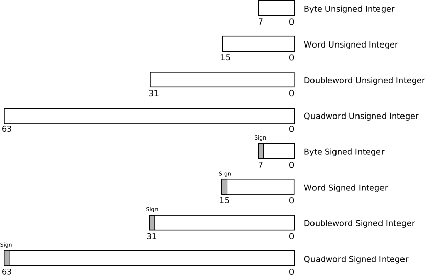
These types are simplest: they are just chunks of memory at different sizes that enable the CPU to access memory efficiently. From the manual, section 4.1.1, volume 1:
Words, doublewords, and quadwords do not need to be aligned in memory on natural boundaries. The natural boundaries for words, double words, and quadwords are even-numbered addresses, addresses evenly divisible by four, and addresses evenly divisible by eight, respectively. However, to improve the performance of programs, data structures (especially stacks) should be aligned on natural boundaries whenever possible. The reason for this is that the processor requires two memory accesses to make an unaligned memory access; aligned accesses require only one memory access. A word or doubleword operand that crosses a 4-byte boundary or a quadword operand that crosses an 8-byte boundary is considered unaligned and requires two separate memory bus cycles for access.
Some instructions that operate on double quadwords require memory operands to be aligned on a natural boundary. These instructions generate a general-protection exception (
#GP) if an unaligned operand is specified. A natural boundary for a double quadword is any address evenly divisible by 16. Other instructions that operate on double quadwords permit unaligned access (without generating a general-protection exception). However, additional memory bus cycles are required to access unaligned data from memory.
In C, the following primitive types (must include
stdint.h) map to the fundamental types:
data.c
#include <stdint.h>

uint8_t byte = 0x12;
uint16_t word = 0x1234;
uint32_t dword = 0x12345678;
uint64_t qword = 0x123456789abcdef;
unsigned __int128 dqword1 =  (__int128) 0x123456789abcdef;
unsigned __int128 dqword2 =  (__int128) 0x123456789abcdef << 64;

int main(int argc, char *argv[]) {
        return 0;
}
This program is the one exception to the compile command above: the
128-bit type only exists when gcc generates 64-bit code, and
gcc $BOOKFLAGS data.c stops with the error
'__int128' is not supported on this target. So, for this
program only, we leave out -m32:
$ gcc -no-pie -fno-pie -fno-asynchronous-unwind-tables -fcf-protection=none -O0 data.c -o data
$ objdump -z -M intel -D -j .data -j .bss data

0000000000404010 <byte>:
  404010:   12 00                   adc    al,BYTE PTR [rax]

0000000000404012 <word>:
  404012:   34 12                   xor    al,0x12

0000000000404014 <dword>:
  404014:   78 56                   js     40406c <_end+0x24>
  404016:   34 12                   xor    al,0x12

0000000000404018 <qword>:
  404018:   ef                      out    dx,eax
  404019:   cd ab                   int    0xab
  40401b:   89 67 45                mov    DWORD PTR [rdi+0x45],esp
  40401e:   23 01                   and    eax,DWORD PTR [rcx]

0000000000404020 <dqword1>:
  404020:   ef                      out    dx,eax
  404021:   cd ab                   int    0xab
  404023:   89 67 45                mov    DWORD PTR [rdi+0x45],esp
  404026:   23 01                   and    eax,DWORD PTR [rcx]
  404028:   00 00                   add    BYTE PTR [rax],al
  40402a:   00 00                   add    BYTE PTR [rax],al
  40402c:   00 00                   add    BYTE PTR [rax],al
  40402e:   00 00                   add    BYTE PTR [rax],al

0000000000404030 <dqword2>:
  404030:   00 00                   add    BYTE PTR [rax],al
  404032:   00 00                   add    BYTE PTR [rax],al
  404034:   00 00                   add    BYTE PTR [rax],al
  404036:   00 00                   add    BYTE PTR [rax],al
  404038:   ef                      out    dx,eax
  404039:   cd ab                   int    0xab
  40403b:   89 67 45                mov    DWORD PTR [rdi+0x45],esp
  40403e:   23 01                   and    eax,DWORD PTR [rcx]
gcc generates the variables byte,
word, dword, qword,
dqword1, dqword2, written earlier, with their
respective values: 12 for byte,
34 12 for word, 78 56 34 12 for
dword, ef cd ab 89 67 45 23 01 for
qword, the same 8 bytes followed by 8 zero bytes for
dqword1, and 8 zero bytes followed by the same 8 bytes for
dqword2. Since this is a data section, the assembly listing
carries no meaning. When byte is declared with
uint8_t, gcc guarantees that the size of
byte is always 1 byte. But, an alert reader might notice
the 00 value next to the 12 value in the
byte variable. This is normal, as gcc avoids
memory misalignment by adding extra padding bytes. To make it
easier to see, we look at readelf output of
.data section:
$ readelf -x .data datathe output is:
Hex dump of section '.data':
  0x00404000 00000000 00000000 00000000 00000000 ................
  0x00404010 12003412 78563412 efcdab89 67452301 ..4.xV4.....gE#.
  0x00404020 efcdab89 67452301 00000000 00000000 ....gE#.........
  0x00404030 00000000 00000000 efcdab89 67452301 ............gE#.
As can be seen in the readelf output, variables are
allocated storage space according to their types and in the declared
order by the programmer: the first 16 bytes belong to the C runtime,
then at 0x404010 come 12 and its padding
00, then 3412, then 78563412, and
so on. Intel is a little-endian machine, which means smaller addresses
hold bytes with smaller values, larger addresses hold bytes with larger
values. For example, 0x1234 is displayed as
34 12; that is, 34 appears first at address
0x404012, then 12 at 0x404013.
The decimal values within a byte are unchanged, so we see
34 12 instead of 43 21. This is quite
confusing at first, but you will get used to it soon.
Also, isn’t it redundant when char type is always 1 byte
already and why do we bother adding int8_t? The truth is,
char type is not guaranteed to be 1 byte in size, but only
the minimum of 1 byte in size. In C, a byte is defined to be the size of
a char, and a char is defined to be the smallest addressable unit of the
underlying hardware platform. There are hardware devices where the
smallest addressable unit is 16 bits or even bigger, which means char is
2 bytes in size and a “byte” in such platforms is actually 2 units of
8-bit bytes.
Not all architectures support the double quadword type. Still,
gcc does provide support for 128-bit numbers and generates
code when a CPU supports it (that is, a CPU must be 64-bit). By
specifying a variable of type __int128 or
unsigned __int128, we get a 128-bit variable. If a CPU does
not support 64-bit mode, or if gcc is asked for 32-bit code with
-m32 as we saw above, gcc throws an error.
The data types in C, which represent the fundamental data types, are also called unsigned numbers. Other than numerical calculations, unsigned numbers are used as a tool for structuring data in memory; we will see this application later on in the book, when various data structures are organized into bit groups.
In all the examples above, when the value of a variable with smaller size is assigned to a variable with larger size, the value easily fits in the larger variable. On the contrary, when the value of a variable with larger size is assigned to a variable with smaller size, two scenarios occur:
The value is greater than the maximum value of the variable with smaller layout, so it needs truncating to the size of the variable, causing an incorrect value.
The value is smaller than the maximum value of the variable with a smaller layout, so it fits the variable.
However, the value might be unknown until runtime and can be any value, so it is best not to let such implicit conversion be handled by the compiler, but explicitly controlled by a programmer. Otherwise it will cause subtle bugs that are hard to catch as the erroneous values might rarely be used to reproduce the bugs.
4.8.2 Pointer Data Types
Pointers are variables that hold memory addresses. x86 works with 2 types of pointers:
- Near pointer
-
is a 16-bit/32-bit offset within a segment, also called effective address.
- Far pointer
-
is also an offset like a near pointer, but with an explicit segment selector.
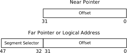
C only provides support for near pointers, since far pointers are platform dependent, such as x86. In application code, you can assume that the address of the current segment starts at 0, so the offset is actually any memory address from 0 to the maximum address.
pointer.c
#include <stdint.h>

int8_t i = 0;
int8_t *p1 =  (int8_t *) 0x1234;
int8_t *p2 =  &i;

int main(int argc, char *argv[]) {
        return 0;
}
$ gcc $BOOKFLAGS pointer.c -o pointer
$ objdump -z -M intel -D -j .data -j .bss pointer
0804c00c <p1>:
804c00c: 34 12 xor al,0x12
804c00e: 00 00 add BYTE PTR [eax],al
0804c010 <p2>:
804c010: 15 .byte 0x15
804c011: c0 .byte 0xc0
804c012: 04 08 add al,0x8
Disassembly of section .bss:
0804c014 <completed.0>:
804c014: 00 add BYTE PTR [eax],al
0804c015 <i>:
804c015: 00 00 add BYTE PTR [eax],al
804c017: 00 .byte 0The pointer p1 holds a direct address with the value
0x1234, stored as the bytes 34 12 00 00. The
pointer p2 holds the address of the variable
i: its bytes 15 c0 04 08 read back to front
give 0x0804c015, which is exactly the address
objdump prints for i in the .bss
section. Note that both pointers are 4 bytes in size (or 8 bytes, in a
64-bit program). i is initialized to 0, which is why it
lives in .bss rather than .data: variables
that start as zero need no storage in the file, only a note of how much
memory to zero out when the program is loaded, as chapter 5 will
show.
4.8.3 Bit Field Data Type
A bit field is a contiguous sequence of bits. Bit fields allow data structuring at bit level. For example, a 32-bit data can hold multiple bit fields that represent multiple different pieces of information, such as bits 0-4 specify the size of a data structure, bits 5-6 specify permissions and so on. Data structures at the bit level are common for low-level programming.
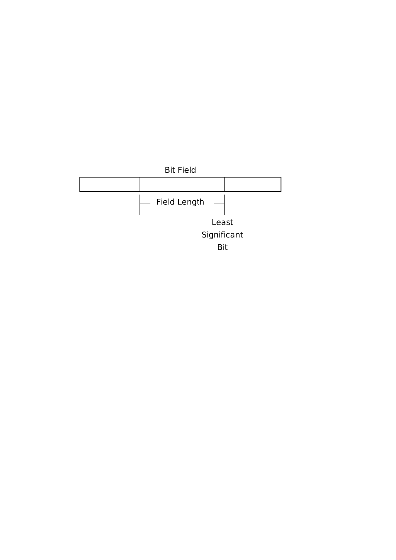
bitfield.c
struct bit_field {
    int data1:8;
    int data2:8;
    int data3:8;
    int data4:8;
};

struct bit_field2 {
    int data1:8;
    int data2:8;
    int data3:8;
    int data4:8;
    char data5:4;
};

struct normal_struct {
    int data1;
    int data2;
    int data3;
    int data4;
};

struct normal_struct ns = {
    .data1 = 0x12345678,
    .data2 = 0x9abcdef0,
    .data3 = 0x12345678,
    .data4 = 0x9abcdef0,
};

int i = 0x12345678;

struct bit_field bf = {
    .data1 = 0x12,
    .data2 = 0x34,
    .data3 = 0x56,
    .data4 = 0x78
};

struct bit_field2 bf2 = {
    .data1 = 0x12,
    .data2 = 0x34,
    .data3 = 0x56,
    .data4 = 0x78,
    .data5 = 0xf
};

int main(int argc, char *argv[]) {
    return 0;
}
$ gcc $BOOKFLAGS bitfield.c -o bitfield
$ objdump -z -M intel -D -j .data -j .bss bitfield
0804c00c <ns>:
804c00c: 78 56 js 804c064 <_end+0x34>
804c00e: 34 12 xor al,0x12
804c010: f0 de bc 9a 78 56 34 lock fidivr WORD PTR [edx+ebx*4+0x12345678]
804c017: 12
804c018: f0 de bc 9a lock fidivr WORD PTR [edx+ebx*4+0x12345678]
804c01f:
0804c01c <i>:
804c01c: 78 56 js 804c074 <_end+0x44>
804c01e: 34 12 xor al,0x12
0804c020 <bf>:
804c020: 12 34 56 adc dh,BYTE PTR [esi+edx*2]
804c023: 78 js 804c037 <_end+0x7>
0804c024 <bf2>:
804c024: 12 34 56 adc dh,BYTE PTR [esi+edx*2]
804c027: 78 0f js 804c038 <_end+0x8>
804c029: 00 00 add BYTE PTR [eax],al
804c02b: 00 .byte 0The sample code creates 4 variables: ns, i,
bf, bf2. The definition of
normal_struct and bit_field structs both
specify 4 integers. bit_field specifies additional
information next to its member name, separated by a colon,
e.g. .data1 : 8. This extra information is the bit width of
each bit group. It means, even though defined as an int,
.data1 only consumes 8 bits of information. If additional
data members are specified after .data1, two scenarios
happen:
If the new data members fit within the remaining bits after
.data1, which are 24 bits8, then the total size ofbit_fieldstruct is still 4 bytes, or 32 bits.If the new data members don’t fit, then the remaining 24 bits (3 bytes) are still allocated. However, the new data members are allocated brand new storage, without using the previous 24 bits.
In the example, the 4 data members: .data1,
.data2, .data3 and .data4, each
can access 8 bits of information, and together can access all of the 4
bytes of the integer first declared by .data1. As can be
seen in the generated assembly code, the values of bf
follow the natural order as written in the C code:
12 34 56 78, since each value is a separate member. In
contrast, the value of i is a number as a whole, so it is
subject to the rule of little endianness and thus contains the value
78 56 34 12.
Note how objdump prints the last byte of
bf, at 804c023: the byte 78
alone, decoded as js 804c037. 78 is the opcode
of js, a conditional jump, and it requires a one-byte
operand. objdump does not know that the symbol
bf ends here, so it grabs whatever the next byte is, the
12 that starts bf2, and decodes
js with it (804c025 + 0x12 = 804c037, the
destination it prints). It then only prints the bytes that belong to
bf, which is why the 12 is not shown in the
raw-bytes column. The same thing happens to the last 4 bytes of
ns at 804c018: objdump consumed
the whole of i as the displacement of a fidivr
instruction, printed only the bytes of ns, and left an
empty line at 804c01f where the rest of that “instruction”
would have been. objdump is a tool to display assembly code
after all; it is just being confused by data. A better tool to use is
gdb that we will learn in chapter 6. But for this chapter,
objdump suffices.
Unlike bf, each data member in ns is
allocated fully as an integer, 4 bytes each, 16 bytes in total. As we
can see, bit field and normal struct are different: bit field structures
data at the bit level, while normal struct works at byte level.
Finally, the struct of bf29 is
the same as bf10, except it contains
one more data member: .data5, and is defined as a
char. For this reason, another 4 bytes are allocated just
for .data5, even though it can only access 4 bits of
information, and the final value of bf2 is:
12 34 56 78 0f 00 00 00. The remaining 3 bytes must be
accessed by means of a pointer, or casting to another data type that can
fully access all 4 bytes.
Exercise 4.4. What happens when the definition of
bit_field struct and bf variable are changed
to:
struct bit_field {
    int data1:8;
};
struct bit_field bf = {
    .data1 = 0x1234,
};
What will be the value of .data1?
Exercise 4.5. What happens when the definition of
bit_field2 struct is changed to:
struct bit_field2 {
    int data1:8;
    int data5:32;
};
What is the layout of a variable of type bit_field2?
4.8.4 String Data Types
Although they share the same name, string as defined by x86 is
different than a string in C. x86 defines string as “continuous
sequences of bits, bytes, words, or doublewords”. On the other
hand, C defines a string as an array of 1-byte characters with a zero as
the last element of the array to make a null-terminated string.
This implies that strings in x86 are arrays, not C strings. A programmer
can define an array of bytes, words or doublewords with
char or uint8_t, short or
uint16_t and int or uint32_t,
except an array of bits. However, such a feature can be easily
implemented, as an array of bits is essentially any array of bytes, or
words or doublewords, but operates at the bit level.
The following code demonstrates how to define array (string) data types:
string.c
#include <stdint.h>

uint8_t a8[2] = {0x12, 0x34};
uint16_t a16[2] = {0x1234, 0x5678};
uint32_t a32[2] = {0x12345678, 0x9abcdef0};
uint64_t a64[2] = {0x123456789abcdef0, 0x123456789abcdef0};

int main(int argc, char *argv[])
{
    return 0;
}
$ gcc $BOOKFLAGS string.c -o string
$ objdump -z -M intel -D -j .data -j .bss string
0804c010 <a8>:
804c010: 12 34 00 adc dh,BYTE PTR [eax+eax*1]
804c013: 00 add BYTE PTR [edx+edx*1],dh
0804c014 <a16>:
804c014: 34 12 xor al,0x12
804c016: 78 56 js 804c06e <_end+0x3a>
0804c018 <a32>:
804c018: 78 56 js 804c070 <_end+0x3c>
804c01a: 34 12 xor al,0x12
804c01c: f0 de bc 9a lock fidivr WORD PTR [edx+ebx*4-0x65432110]
804c023:
0804c020 <a64>:
804c020: f0 de bc 9a 78 56 34 lock fidivr WORD PTR [edx+ebx*4+0x12345678]
804c027: 12
804c028: f0 de bc 9a 78 56 34 lock fidivr WORD PTR [edx+ebx*4+0x12345678]
804c02f: 12 Despite a8 being an array with 2 elements, each 1 byte
long, it is still allocated with 4 bytes. Again, to ensure natural
alignment for best performance, gcc pads extra zero bytes.
As shown in the assembly listing, the actual value of a8 is
12 34 00 00, with a8[0] equal to
12 and a8[1] equal to 34.
Then it comes a16 with 2 elements, each 2 bytes long.
Since 2 elements are 4 bytes in total, which is in the natural
alignment, gcc pads no byte. The value of a16
is 34 12 78 56, with a16[0] equal to
34 12 and a16[1] equal to
78 56.
Next is a32, with 2 elements, 4 bytes each. Similar to
the above arrays, the value of a32[0] is
78 56 34 12, the value of a32[1] is
f0 de bc 9a, exactly what is assigned in the C code. Note
that objdump is confused again, as de is the
opcode for the instruction fidivr (short for reverse
divide) that requires another operand, so objdump grabs
whatever the next bytes are that make sense to it for creating “an
operand”, here the first 4 bytes of a64, and leaves an
empty line at 804c023. Only the bytes
f0 de bc 9a printed at 804c01c belong to
a32.
Finally is a64, also with 2 elements, but 8 bytes each.
The total size of a64 is 16 bytes, which is in the natural
alignment, therefore no padding bytes are added. The values of both
a64[0] and a64[1] are the same:
f0 de bc 9a 78 56 34 12, that got misinterpreted as a
fidivr instruction.
| array | layout in memory |
|---|---|
a8 |
12 | 34 |
00 00 (padding) |
a16 |
34 12 |
78 56 |
a32 |
78 56 34 12 |
f0 de bc 9a |
a64 |
f0 de bc 9a 78 56 34 12 |
f0 de bc 9a 78 56 34 12 |
However, beyond one-dimensional arrays that map directly to hardware string type, C provides its own syntax for multi-dimensional arrays:
array.c
#include <stdint.h>

uint8_t a2[2][2] = {
    {0x12, 0x34},
    {0x56, 0x78}
};

uint8_t a3[2][2][2] = {
    {{0x12, 0x34},
     {0x56, 0x78}},
    {{0x9a, 0xbc},
     {0xde, 0xff}},
};

int main(int argc, char *argv[]) {
    return 0;
}
$ gcc $BOOKFLAGS array.c -o array
$ objdump -z -M intel -D -j .data -j .bss array
0804c00c <a2>:
804c00c: 12 34 56 adc dh,BYTE PTR [esi+edx*2]
804c00f: 78 js 804c023 <_end+0x7>
0804c010 <a3>:
804c010: 12 34 56 adc dh,BYTE PTR [esi+edx*2]
804c013: 78 9a js 804bfaf <_DYNAMIC+0xa7>
804c015: bc .byte 0xbc
804c016: de ff fdivp st(7),stTechnically, multi-dimensional arrays are like normal arrays: in the
end, the total size is translated into flat allocated bytes. A 2 x 2
array is allocated with 4 bytes; a 2 x 2 x 2 array is allocated with 8
bytes, as can be seen in the assembly listing of a211 and a3. In low-level
assembly code, the representation is the same between a[4]
and a[2][2]. However, in high-level C code, the difference
is tremendous. The syntax of multi-dimensional arrays enables a
programmer to think with higher level concepts, instead of translating
manually from high-level concepts to low-level code and working with
high-level concepts in his head at the same time.
Example 4.11. The following two-dimensional array can hold a list of 2 names with the length of 10:
char names[2][10] = {
    "John Doe",
    "Jane Doe"
};
To access a name, we simply adjust the column index12
e.g. names[0], names[1]. To access an
individual character within a name, we use the row index13
e.g. names[0][0] gives the character “J”,
names[0][1] gives the character “o” and so on.
Without such syntax, we need to create a 20-byte array
e.g. names[20], and whenever we want to access a character
e.g. to check if a name contains a number in it, we need to calculate
the index manually. It would be distracting, since we constantly need to
switch our thinking between the actual problem and the translation
problem.
Since this is a repeating pattern, C abstracts away this problem with the syntax for defining and manipulating multi-dimensional arrays. Through this example, we can clearly see the power that abstraction through language can give us. It would be ideal if a programmer were equipped with such power to define whatever syntax is suitable for a problem at hand. Not many languages provide such capacity. Fortunately, through C macros, we can partially achieve that goal.
In all cases, an array is guaranteed to generate contiguous bytes of memory, regardless of the dimensions it has.
Exercise 4.6. What is the difference between a multi-dimensional array and an array of pointers, or even pointers of pointers?
4.9 Examine compiled code
This section will explore how a compiler transforms high level code
into assembly code that the CPU can execute, and see how common assembly
patterns help to create higher level syntax. -S option is
added to objdump to better demonstrate the connection
between high and low level code, which requires compiling with
-g:
$ gcc $BOOKFLAGS -g <source file> -o <object file>In this section, the option --no-show-raw-insn is added
to the objdump command to omit the opcodes for clarity:
$ objdump --no-show-raw-insn -M intel -S -D <object file> | lessAs before, the listings are cut down to the functions of our
programs; the many functions the C runtime adds (_start,
deregister_tm_clones, …) are not shown.
4.9.1 Data Transfer
The previous section explored how various types of data are created, and how they are laid out in memory. Once memory storage is allocated for variables, it must be accessible and writable. Data transfer instructions move data (bytes, words, doublewords or quadwords) between memory and registers, and between registers, effectively reading from a storage source and writing to another storage source.
transfer.c
#include <stdint.h>

int32_t i = 0x12345678;

int main(int argc, char *argv[]) {
        int j = i;
        int k = 0xabcdef;

        return 0;
}
$ gcc $BOOKFLAGS -g transfer.c -o transfer
$ objdump --no-show-raw-insn -M intel -S -D transfer
08049156 <main>:
#include <stdint.h>
int32_t i = 0x12345678;
int main(int argc, char *argv[]) {
8049156: push ebp
8049157: mov ebp,esp
8049159: sub esp,0x10
int j = i;
804915c: mov eax,ds:0x804c00c
8049161: mov DWORD PTR [ebp-0x4],eax
int k = 0xabcdef;
8049164: mov DWORD PTR [ebp-0x8],0xabcdef
return 0;
804916b: mov eax,0x0
}
8049170: leave
8049171: retThe general data movement is performed with the mov
instruction. Note that despite the instruction being called
mov, it actually copies data from one place to another.
The instruction at 8049157 copies data from the register
esp to the register ebp. This mov
instruction moves data between registers and is assigned the opcode
89.
The two instructions at 804915c and 8049161
copy data from one memory location (the i variable, at the
address 0x804c00c in the .data section) to
another (the j variable, at [ebp-0x4] on the
stack). There exists no data movement from memory to memory; it requires
two mov instructions, one for copying the data from a
memory location to a register, and one for copying the data from the
register to the destination memory location.
The instruction at 8049164 copies an immediate value
into memory, the variable k at [ebp-0x8].
Finally, the instruction at 804916b copies immediate data
into a register: this is how main returns 0,
as the next sections will explain.
4.9.2 Expressions
expr.c
int expr(int i, int j)
{
    int add            = i + j;
    int sub            = i - j;
    int mul            = i * j;
    int div            = i / j;
    int mod            = i % j;
    int neg            = -i;
    int and            = i & j;
    int or             = i | j;
    int xor            = i ^ j;
    int not            = ~i;
    int shl            = i << 8;
    int shr            = i >> 8;
    char equal1        = (i == j);
    int equal2         = (i == j);
    char greater       = (i > j);
    char less          = (i < j);
    char greater_equal = (i >= j);
    char less_equal    = (i <= j);
    int logical_and    = i && j;
    int logical_or     = i || j;
    ++i;
    --i;
    int i1             = i++;
    int i2             = ++i;
    int i3             = i--;
    int i4             = --i;

    return 0;
}

int main(int argc, char *argv[]) {
    return 0;
}
$ gcc $BOOKFLAGS -g expr.c -o expr
$ objdump --no-show-raw-insn -M intel -S -D exprThe full assembly listing is really long. For that reason, we examine
expression by expression. gcc reserves space for all the
local variables at once when expr starts, with
sub esp,0x60, and assigns each variable a slot below
ebp in the order of declaration: add at
[ebp-0x4], sub at [ebp-0x8], and
so on. The two arguments i and j are at
[ebp+0x8] and [ebp+0xc]; the section on
automatic variables below explains why.
Expression int add = i + j;
 804915c:   mov    edx,DWORD PTR [ebp+0x8]
 804915f:   mov    eax,DWORD PTR [ebp+0xc]
 8049162:   add    eax,edx
 8049164:   mov    DWORD PTR [ebp-0x4],eax
The assembly code is straightforward: variables i and
j are loaded into edx and eax
respectively, then added together with the add instruction,
and the final result is stored into eax. Then, the result
is saved into the local variable add, which is at the
location [ebp-0x4].
Expression int sub = i - j;
 8049167:   mov    eax,DWORD PTR [ebp+0x8]
 804916a:   sub    eax,DWORD PTR [ebp+0xc]
 804916d:   mov    DWORD PTR [ebp-0x8],eax
Similar to add instruction, x86 provides a
sub instruction for subtraction. Hence, gcc
translates a subtraction into sub instruction, with
eax reloaded with i, as eax still
carries the result from the previous expression. Then, j is
subtracted from i. After the subtraction, the value is
saved into the variable sub, at location
[ebp-0x8].
Expression int mul = i * j;
 8049170:   mov    eax,DWORD PTR [ebp+0x8]
 8049173:   imul   eax,DWORD PTR [ebp+0xc]
 8049177:   mov    DWORD PTR [ebp-0xc],eax
Similar to sub instruction, only eax is
reloaded, since it carries the result of the previous calculation.
imul performs signed multiply14.
eax is first loaded with i, then is multiplied
with j and the result stored back into eax,
then stored into the variable mul at location
[ebp-0xc].
Expression int div = i / j;
 804917a:   mov    eax,DWORD PTR [ebp+0x8]
 804917d:   cdq
 804917e:   idiv   DWORD PTR [ebp+0xc]
 8049181:   mov    DWORD PTR [ebp-0x10],eax
Similar to imul, idiv performs signed
divide. But, different from imul above, idiv
only takes one operand:
First,
iis reloaded intoeax.Then,
cdqconverts the double word value ineaxinto a quadword value stored in the pair of registersedx:eax, by copying the sign (bit 31) of the value ineaxinto every bit position inedx. The pairedx:eaxis the dividend, which is the variablei, and the operand toidivis the divisor, which is the variablej.After the calculation, the result is stored into the pair
edx:eaxregisters, with the quotient ineaxand remainder inedx. The quotient is stored in the variablediv, at location[ebp-0x10].
Expression int mod = i % j;
 8049184:   mov    eax,DWORD PTR [ebp+0x8]
 8049187:   cdq
 8049188:   idiv   DWORD PTR [ebp+0xc]
 804918b:   mov    DWORD PTR [ebp-0x14],edx
The same idiv instruction also performs the modulo
operation, since it also calculates a remainder and stores it in the
variable mod, at location [ebp-0x14].
Expression int neg = -i;
 804918e:   mov    eax,DWORD PTR [ebp+0x8]
 8049191:   neg    eax
 8049193:   mov    DWORD PTR [ebp-0x18],eax
neg replaces the value of the operand (the destination
operand) with its two’s complement (this operation is equivalent to
subtracting the operand from 0). In this example, the value
i in eax is replaced with -i
using neg instruction. Then, the new value is stored in the
variable neg at [ebp-0x18].
Expression int and = i & j;
 8049196:   mov    eax,DWORD PTR [ebp+0x8]
 8049199:   and    eax,DWORD PTR [ebp+0xc]
 804919c:   mov    DWORD PTR [ebp-0x1c],eax
and performs a bitwise AND operation on two
operands, and stores the result in the destination operand, which is the
variable and at [ebp-0x1c].
Expression int or = i | j;
 804919f:   mov    eax,DWORD PTR [ebp+0x8]
 80491a2:   or     eax,DWORD PTR [ebp+0xc]
 80491a5:   mov    DWORD PTR [ebp-0x20],eax
Similar to and instruction, or performs a
bitwise OR operation on two operands, and stores the result
in the destination operand, which is the variable or at
[ebp-0x20] in this case.
Expression int xor = i ^ j;
 80491a8:   mov    eax,DWORD PTR [ebp+0x8]
 80491ab:   xor    eax,DWORD PTR [ebp+0xc]
 80491ae:   mov    DWORD PTR [ebp-0x24],eax
Similar to and/or instruction,
xor performs a bitwise XOR operation on two
operands, and stores the result in the destination operand, which is the
variable xor at [ebp-0x24].
Expression int not = ~i;
 80491b1:   mov    eax,DWORD PTR [ebp+0x8]
 80491b4:   not    eax
 80491b6:   mov    DWORD PTR [ebp-0x28],eax
not performs a bitwise NOT operation (each
1 is set to 0, and each 0 is set to 1) on the destination operand and
stores the result in the destination operand location, which is the
variable not at [ebp-0x28].
Expression int shl = i << 8;
 80491b9:   mov    eax,DWORD PTR [ebp+0x8]
 80491bc:   shl    eax,0x8
 80491bf:   mov    DWORD PTR [ebp-0x2c],eax
shl (shift logical left) shifts the bits in the
destination operand to the left by the number of bits specified in the
source operand. In this case, eax stores i and
shl shifts eax by 8 bits to the left. A
different name for shl is sal (shift
arithmetic left). Both can be used synonymously. Finally, the result is
stored in the variable shl at [ebp-0x2c].
Here is a visual demonstration of shl/sal
and shr instructions:
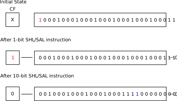

After shifting to the left, the last bit shifted out is stored in the
Carry Flag of EFLAGS register.
Expression int shr = i >> 8;
 80491c2:   mov    eax,DWORD PTR [ebp+0x8]
 80491c5:   sar    eax,0x8
 80491c8:   mov    DWORD PTR [ebp-0x30],eax
sar is similar to shl/sal, but
shifts bits to the right and extends the sign bit. For right shift,
shr and sar are two different instructions.
shr differs from sar in that it does not
extend the sign bit. Finally, the result is stored in the variable
shr at [ebp-0x30].
In the SHR figure, notice that initially, the sign bit
is 1, but after 1-bit and 10-bit shiftings, the shifted-in bits are
filled with zeros.
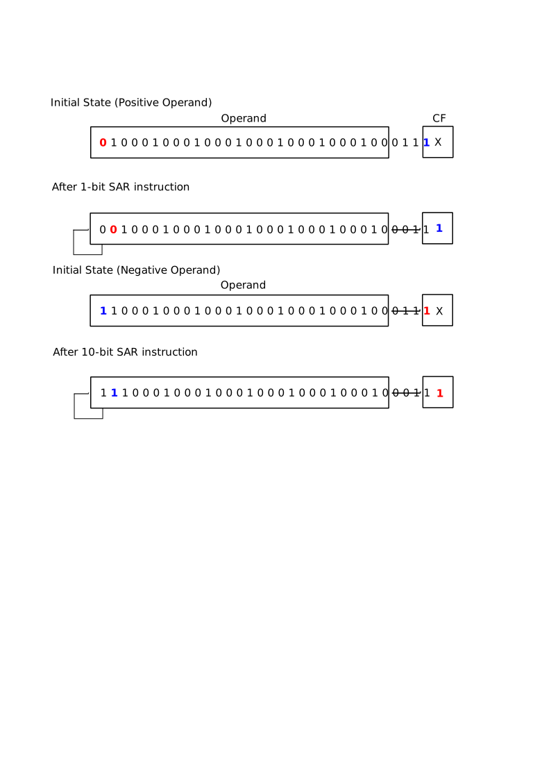
With sar, the sign bit (the most significant bit) is
preserved. That is, if the sign bit is 0, the new bits always get the
value 0; if the sign bit is 1, the new bits always get the value 1.
Expression char equal1 = (i == j);
 80491cb:   mov    eax,DWORD PTR [ebp+0x8]
 80491ce:   cmp    eax,DWORD PTR [ebp+0xc]
 80491d1:   sete   al
 80491d4:   mov    BYTE PTR [ebp-0x31],al
cmp and the variants of set instructions
make up all the logical comparisons. In this expression,
cmp compares variables i and j;
then sete stores the value 1 to al register if
the comparison from cmp earlier is equal, or stores 0
otherwise. The general name for variants of set instruction
is SETcc. The suffix cc denotes the condition
being tested for in EFLAGS register. Appendix B in volume
1, “EFLAGS Condition Codes”, lists the conditions it is
possible to test for with this instruction. Finally, the result is
stored in the variable equal1 at [ebp-0x31]: a
char is a single byte, so this variable takes one byte
right below shr.
Expression int equal2 = (i == j);
 80491d7:   mov    eax,DWORD PTR [ebp+0x8]
 80491da:   cmp    eax,DWORD PTR [ebp+0xc]
 80491dd:   sete   al
 80491e0:   movzx  eax,al
 80491e3:   mov    DWORD PTR [ebp-0x38],eax
Similar to the equality comparison above, this expression also
compares for equality, with the exception that the result is stored in
an int type. For that reason, one more instruction is
added: movzx instruction, a variant of mov
that copies the result into a destination operand and fills the
remaining bytes with 0. In this case, since eax is 4 bytes
wide, after copying the first byte in al, the remaining
bytes of eax are filled with 0 to ensure that
eax carries the same value as al. Also note
that equal2 lives at [ebp-0x38], not
[ebp-0x35] right after equal1:
gcc keeps every int on a 4-byte boundary,
exactly the natural alignment the Intel manual recommended above.
| byte 3 | byte 2 | byte 1 | byte 0 | |
|---|---|---|---|---|
(a) eax before
movzx |
12 |
34 |
56 |
78 |
(b) after movzx eax, al |
00 |
00 |
00 |
78 |
Expression char greater = (i > j);
 80491e6:   mov    eax,DWORD PTR [ebp+0x8]
 80491e9:   cmp    eax,DWORD PTR [ebp+0xc]
 80491ec:   setg   al
 80491ef:   mov    BYTE PTR [ebp-0x39],al
Similar to the equality comparison, but using setg for
greater comparison instead.
Expression char less = (i < j);
 80491f2:   mov    eax,DWORD PTR [ebp+0x8]
 80491f5:   cmp    eax,DWORD PTR [ebp+0xc]
 80491f8:   setl   al
 80491fb:   mov    BYTE PTR [ebp-0x3a],al
Applies setl for less comparison.
Expression char greater_equal = (i >= j);
 80491fe:   mov    eax,DWORD PTR [ebp+0x8]
 8049201:   cmp    eax,DWORD PTR [ebp+0xc]
 8049204:   setge  al
 8049207:   mov    BYTE PTR [ebp-0x3b],al
Applies setge for greater or
equal comparison.
Expression char less_equal = (i <= j);
 804920a:   mov    eax,DWORD PTR [ebp+0x8]
 804920d:   cmp    eax,DWORD PTR [ebp+0xc]
 8049210:   setle  al
 8049213:   mov    BYTE PTR [ebp-0x3c],al
Applies setle for less than or
equal comparison.
Expression int logical_and = i && j;
 8049216:   cmp    DWORD PTR [ebp+0x8],0x0
 804921a:   je     8049229 <expr+0xd3>
 804921c:   cmp    DWORD PTR [ebp+0xc],0x0
 8049220:   je     8049229 <expr+0xd3>
 8049222:   mov    eax,0x1
 8049227:   jmp    804922e <expr+0xd8>
 8049229:   mov    eax,0x0
 804922e:   mov    DWORD PTR [ebp-0x40],eax
Logical AND operator && is one of
the syntaxes that is made entirely in software15
with simpler instructions. The algorithm from the assembly code is
simple:
First, check if
iis0with the instruction at8049216.If true, jump to
8049229and seteaxto 0.Set the variable
logical_andto 0, as it is the next instruction after8049229.
If
iis not0, check ifjis0with the instruction at804921c.If true, jump to
8049229and seteaxto 0.Set the variable
logical_andto 0, as it is the next instruction after8049229.
If both
iandjare not0, the result is certainly1, ortrue.Set it accordingly with the instruction at
8049222.Then jump to the instruction at
804922eto set the variablelogical_andat[ebp-0x40]to 1.
Expression int logical_or = i || j;
 8049231:   cmp    DWORD PTR [ebp+0x8],0x0
 8049235:   jne    804923d <expr+0xe7>
 8049237:   cmp    DWORD PTR [ebp+0xc],0x0
 804923b:   je     8049244 <expr+0xee>
 804923d:   mov    eax,0x1
 8049242:   jmp    8049249 <expr+0xf3>
 8049244:   mov    eax,0x0
 8049249:   mov    DWORD PTR [ebp-0x44],eax
Logical OR operator || is similar to
logical and above. Understanding the algorithm is left as an exercise
for readers.
Expression ++i; and --i; (or
i++ and i--)
 804924c:   add    DWORD PTR [ebp+0x8],0x1
 8049250:   sub    DWORD PTR [ebp+0x8],0x1
The syntax of increment and decrement is similar to logical
AND and logical OR in that it is made from
existing instructions, that is add and sub.
The difference is that the CPU actually does have built-in instructions,
inc and dec, but gcc decided not
to use them because inc and dec cause a
partial flag register stall, which occurs when an instruction
modifies a part of the flag register and the following instruction is
dependent on the outcome of the flags (section 3.5.2.6, (Intel
2016)). The manual even suggests that inc and
dec should be replaced with add and
sub instructions (section 3.5.1.1, (Intel
2016)).
Expression int i1 = i++;
 8049254:   mov    eax,DWORD PTR [ebp+0x8]
 8049257:   lea    edx,[eax+0x1]
 804925a:   mov    DWORD PTR [ebp+0x8],edx
 804925d:   mov    DWORD PTR [ebp-0x48],eax
First, i is copied into eax at
8049254. Then, the value of eax + 0x1 is
copied into edx as an effective address at
8049257. The lea (load effective
address) instruction copies a memory address into a register.
According to Volume 2, the source operand is a memory address specified
with one of the processor’s addressing modes. This means, the source
operand must be specified by the addressing modes defined in the 16-bit and 32-bit
ModR/M tables. Here gcc uses it as a cheap way
to compute eax + 1 into another register without touching
eax and without touching the flags.
After loading the incremented value into edx, the value
of i is increased by 1 at 804925a. Finally,
the previous i value is stored back to
i1 at [ebp-0x48] by the instruction at
804925d.
Expression int i2 = ++i;
 8049260:   add    DWORD PTR [ebp+0x8],0x1
 8049264:   mov    eax,DWORD PTR [ebp+0x8]
 8049267:   mov    DWORD PTR [ebp-0x4c],eax
The primary differences between this increment syntax and the previous one are:
addis used instead ofleato increaseidirectly.the newly incremented
iis stored intoi2instead of the old value.the expression only costs 3 instructions instead of 4.
This prefix-increment syntax is faster than the postfix one used
previously. It might not matter much which version to use if the
increment is only used once or a few hundred times in a small loop, but
it matters when a loop runs millions or more times. Also, depending on
different circumstances, it is more convenient to use one over the other
e.g. if i is an index for accessing an array, we want to
use the old value for accessing the previous array element and the newly
incremented i for the current element.
Expression int i3 = i--;
 804926a:   mov    eax,DWORD PTR [ebp+0x8]
 804926d:   lea    edx,[eax-0x1]
 8049270:   mov    DWORD PTR [ebp+0x8],edx
 8049273:   mov    DWORD PTR [ebp-0x50],eax
Similar to i++ syntax, and is left as an exercise to
readers.
Expression int i4 = --i;
 8049276:   sub    DWORD PTR [ebp+0x8],0x1
 804927a:   mov    eax,DWORD PTR [ebp+0x8]
 804927d:   mov    DWORD PTR [ebp-0x54],eax
Similar to ++i syntax, and is left as an exercise to
readers.
Exercise 4.7. Read the section “Partial Register Stalls” (section 3.5.2.4 at the time of writing) in the Intel 64 and IA-32 Architectures Optimization Reference Manual, a separate document from the three volumes of the software developer’s manual, to understand register stalls in general.
Exercise 4.8. Read the sections from 7.3.1 to 7.3.7 in volume 1.
4.9.3 Stack
A stack is a contiguous array of memory locations that holds a
collection of discrete data. When a new element is added, a stack
grows down in memory toward lesser addresses, and shrinks
up toward greater addresses when an element is removed. x86 uses
the esp register to point to the top of the stack, at the
newest element. A stack can be originated anywhere in main memory, as
esp can be set to any memory address. x86 provides two
operations for manipulating stacks:
pushinstruction and its variants add a new element on top of the stackpopinstructions and its variants remove the top-most element from the stack.
| address | (a) initial state | (b) after
push word 0x5678 |
(c) after pop word |
|---|---|---|---|
0x10000 |
00 |
00 |
00 |
0x10001 |
00 |
00 |
00 |
0x10002 |
00 |
78 ← esp |
78 |
0x10003 |
00 |
56 |
56 |
0x10004 |
12 ← esp |
12 |
12 ← esp |
4.9.4 Automatic variables
Local variables are variables that exist within a scope. A scope is
delimited by a pair of braces: {..}. The most common scope
to define local variables is at function scope. However, a scope can be
unnamed, and variables created inside an unnamed scope do not exist
outside of its scope and its inner scope.
Example 4.12. Function scope:
void foo() {
    int a;
    int b;
}
a and b are variables local to the function
foo.
Example 4.13. Unnamed scope:
int foo() {
    int i;

    {
        int a = 1;
        int b = 2;
        {
            return i = a + b;
        }
    }
}
a and b are local to where they are defined
and to the inner child scope that returns i = a + b.
However, they do not exist at the function scope that creates
i.
When a local variable is created, it is pushed on the stack; when a local variable goes out of scope, it is popped out of the stack, thus destroyed. When an argument is passed from a caller to a callee, it is pushed on the stack; when a callee returns to the caller, the arguments are popped out of the stack. The local variables and arguments are automatically allocated upon entering a function and destroyed after exiting a function, that’s why they are called automatic variables.
A base frame pointer points to the start of the current function
frame, and is kept in ebp register. Whenever a function is
called, it is allocated with its own dedicated storage on the stack,
called stack frame. A stack frame is where all local variables
and arguments of a function are placed on a stack16.
When a function needs a local variable or an argument, it uses
ebp to access a variable:
All local variables are allocated after the
ebppointer. Thus, to access a local variable, a number is subtracted fromebpto reach the location of the variable.All arguments are allocated before the
ebppointer. To access an argument, a number is added toebpto reach the location of the argument.The
ebppointer itself points to the savedebpof its caller, and right above it is the return address into the caller.
| arguments (previous frame) | ebp ↓ |
local variables (current frame) | |
|---|---|---|---|
An ........
A3 A2 A1 |
Return address |
Old ebp |
L1 L2
L3 ........ Ln |
A = Argument
L = Local Variable
Here is an example to make it more concrete:
add.c
#include <stdint.h>

int add(int a, int b) {
    int i = a + b;

    return i;
}

int main(int argc, char *argv[]) {
    return add(1, 2);
}
$ gcc $BOOKFLAGS -g add.c -o add
$ objdump --no-show-raw-insn -M intel -S -D add
08049156 <add>:
#include <stdint.h>
int add(int a, int b) {
8049156: push ebp
8049157: mov ebp,esp
8049159: sub esp,0x10
int i = a + b;
804915c: mov edx,DWORD PTR [ebp+0x8]
804915f: mov eax,DWORD PTR [ebp+0xc]
8049162: add eax,edx
8049164: mov DWORD PTR [ebp-0x4],eax
return i;
8049167: mov eax,DWORD PTR [ebp-0x4]
}
804916a: leave
804916b: retIn the assembly listing, [ebp-0x4] is the local variable
i, since it is allocated after ebp,
with the length of 4 bytes (an int). On the other hand,
a and b are arguments and can be accessed with
ebp:
[ebp+0x8]accessesa.[ebp+0xc]accessesb.
For accessing arguments, the rule is that the closer a variable on
the stack is to ebp, the closer it is to the function
name.
Suppose that ebp holds 0x10000 while
add runs. Then the frame of add looks like
this in memory, highest address first, as the Intel manuals draw
stacks:
| addresses | content | reached as |
|---|---|---|
0x1000c -
0x1000f |
b
(02 00 00 00) |
[ebp+0xc] |
0x10008 -
0x1000b |
a
(01 00 00 00) |
[ebp+0x8] |
0x10004 -
0x10007 |
return address into main |
[ebp+0x4] |
0x10000 -
0x10003 |
old ebp (of
main) |
[ebp], ebp
points here |
0xfffc -
0xffff |
i
(03 00 00 00) |
[ebp-0x4] |
0xfff0 -
0xfffb |
unused, reserved by
sub esp,0x10 |
esp points to
0xfff0 |
From the table, we can see that a and b are
laid out in memory in the exact order as written in C, relative to the
return address. The 12 bytes below i are reserved by
sub esp,0x10 but never used: gcc rounds the
frame up to 16 bytes to keep esp aligned, which the ABI
requires at the moment a function is called.
4.9.5 Function Call and Return
call.c
#include <stdio.h>

int add(int a, int b) {
    int local = 0x12345;

    return a + b;
}

int main(int argc, char *argv[]) {
    add(1,1);

    return 0;
}
$ gcc $BOOKFLAGS -g call.c -o call
$ objdump --no-show-raw-insn -M intel -S -D callFor every function call, gcc pushes arguments on the
stack in reverse order with push instructions. That is, the
arguments pushed on the stack are in reverse order as they are written
in high level C code, to ensure the relative order between arguments, as
seen in the previous section where function arguments and local
variables are laid out. Then, gcc generates a
call instruction, which then implicitly pushes a return
address before transferring the control to add
function:
0804916d <main>:

int main(int argc, char *argv[]) {
 804916d:   push   ebp
 804916e:   mov    ebp,esp
    add(1,1);
 8049170:   push   0x1
 8049172:   push   0x1
 8049174:   call   8049156 <add>
 8049179:   add    esp,0x8

    return 0;
 804917c:   mov    eax,0x0
}
 8049181:   leave
 8049182:   ret
Both arguments are 1 here, so the two push
instructions look alike; the one at 8049170 pushes
b, the one at 8049172 pushes a.
Upon finishing the call to add function, the stack is
restored by adding 0x8 to the stack pointer
esp (which is equivalent to 2 pop
instructions). Finally, a leave instruction is executed and
main returns with a ret instruction. A
ret instruction transfers the program execution back to the
caller, to the instruction right after the call
instruction, the add esp,0x8 instruction. The reason
ret can return to such a location is that the return
address is implicitly pushed by the call instruction, which
is the address right after the call instruction; whenever
the CPU executes a ret instruction, it retrieves the return
address that sits right after all the arguments on the stack.
At the end of a function, gcc places a
leave instruction to clean up all spaces allocated for
local variables and restore the frame pointer to the frame pointer of
the caller. leave is a shorthand for
mov esp,ebp followed by pop ebp, the exact
reverse of the push ebp / mov ebp,esp that
opens every function. Notice that main has no local
variable, so there is no sub esp,... after its
mov ebp,esp, but gcc still closes it with
leave:
08049156 <add>:
#include <stdio.h>

int add(int a, int b) {
 8049156:   push   ebp
 8049157:   mov    ebp,esp
 8049159:   sub    esp,0x10
    int local = 0x12345;
 804915c:   mov    DWORD PTR [ebp-0x4],0x12345

    return a + b;
 8049163:   mov    edx,DWORD PTR [ebp+0x8]
 8049166:   mov    eax,DWORD PTR [ebp+0xc]
 8049169:   add    eax,edx
}
 804916b:   leave
 804916c:   ret
Exercise 4.9. The above code that gcc
generated for function calling is actually the standard method x86
defined. Read chapter 6, “Procedure Calls, Interrupts, and
Exceptions”, Intel manual volume 1.
4.9.6 Loop
A loop is simply resetting the instruction pointer to an already
executed instruction and starting from there all over again. A loop is
just one application of jmp instruction. However, because
looping is a pervasive pattern, it earned its own syntax in C.
loop.c
#include <stdio.h>

int main(int argc, char *argv[]) {
    for (int i = 0; i < 10; i++) {
    }

    return 0;
}
$ gcc $BOOKFLAGS -g loop.c -o loop
$ objdump --no-show-raw-insn -M intel -S -D loop
08049156 <main>:
#include <stdio.h>
int main(int argc, char *argv[]) {
8049156: push ebp
8049157: mov ebp,esp
8049159: sub esp,0x10
for (int i = 0; i < 10; i++) {
804915c: mov DWORD PTR [ebp-0x4],0x0
8049163: jmp 8049169 <main+0x13>
8049165: add DWORD PTR [ebp-0x4],0x1
8049169: cmp DWORD PTR [ebp-0x4],0x9
804916d: jle 8049165 <main+0xf>
}
return 0;
804916f: mov eax,0x0
}
8049174: leave
8049175: retThe instructions map to the high level code as follows:
The instruction at
804915cinitializesito0, then thejmpat8049163goes straight to the comparison.The instructions at
8049169and804916dcompareito 10, by usingjleto compare it to9. If true, jump to8049165for another iteration.The instruction at
8049165increasesiby 1, making the loop able to terminate once the termination condition is satisfied.
Exercise 4.10. Why does the increment instruction
(at 8049165) appear before the compare instructions (at
8049169 and 804916d)?
Exercise 4.11. What assembly code can be generated
for while and do...while?
4.9.7 Conditional
Again, a conditional in C with if...else... construct is
just another application of jmp instruction under the hood.
It is also a pervasive pattern that earned its own syntax in C.
cond.c
#include <stdio.h>

int main(int argc, char *argv[]) {
    int i = 0;

    if (argc) {
        i = 1;
    } else {
        i = 0;
    }

    return 0;
}
$ gcc $BOOKFLAGS -g cond.c -o cond
$ objdump --no-show-raw-insn -M intel -S -D cond
08049156 <main>:
#include <stdio.h>
int main(int argc, char *argv[]) {
8049156: push ebp
8049157: mov ebp,esp
8049159: sub esp,0x10
int i = 0;
804915c: mov DWORD PTR [ebp-0x4],0x0
if (argc) {
8049163: cmp DWORD PTR [ebp+0x8],0x0
8049167: je 8049172 <main+0x1c>
i = 1;
8049169: mov DWORD PTR [ebp-0x4],0x1
8049170: jmp 8049179 <main+0x23>
} else {
i = 0;
8049172: mov DWORD PTR [ebp-0x4],0x0
}
return 0;
8049179: mov eax,0x0
}
804917e: leave
804917f: retThe generated assembly code follows the same order as the corresponding high level syntax:
the instructions from
8049163to8049170represent theifbranch.the instruction at
8049172represents theelsebranch.the instruction at
8049179is the exit point for bothifandelsebranches.
The if branch first compares whether argc
is false (equal to 0) with cmp instruction. If
true, it proceeds to the else branch at
8049172. Otherwise, the if branch continues
with the code of its branch, which is the next instruction at
8049169 for copying 1 to i.
Finally, it skips over the else branch and proceeds to
8049179, which is the next instruction past the
if...else... construct.
The else branch is entered when the cmp
instruction from the if branch is true. The
else branch starts at 8049172, which is its
first instruction. The instruction copies 0 to
i, and proceeds naturally to the next instruction past the
if...else... construct without any jump.
4.10 Check your understanding
Without a
bits 32line,add eax, ecxassembles to66 01 c8(example 4.5). What would the bytes be withbits 32at the top of the file, and what would a processor running in 32-bit mode do with the three bytes66 01 c8?A displacement and an immediate are both constants stored inside the instruction. What is the difference between them, and how does the processor tell them apart in
mov DWORD PTR [ebp-0x8],0xabcdeffromtransfer.c, which contains both?The first
jmp mainof the example in the section on thejmpinstruction assembles toeb fe. Why does the processor not need the address ofmainto execute it, what does that buy when the same code is loaded at another address, and which kinds of jump do need an absolute address?In
data.c,byteat0x404010is followed by a padding byte beforewordat0x404012. What would the layout be ifwordwere declared beforebyte, and why does the compiler bother with padding at all?i / jandi % jcompile to the samecdqandidivpair; only the register stored afterwards differs. What doescdqdo, and what would happen if it were left out andiwere negative?In
add.c, the first argument is at[ebp+0x8], not at[ebp]. What occupies the eight bytes in between, where would a third argument be, and why are the arguments pushed in reverse order?After
call add,mainexecutesadd esp,0x8. Why is it the caller and not the callee that removes the arguments from the stack, and how could the callee do it instead?for (int i = 0; i < 10; i++)compiles tocmp DWORD PTR [ebp-0x4],0x9followed byjle. What changes ifiis declaredunsigned int, and why does thecmpinstruction itself not change?
The output from
hd.↩︎Remember, using
binformat generates 16-bit code by default.↩︎Look at the note under the table in volume 2: with
mod=00, a base of101means “no base register, 32-bit displacement follows”.↩︎The byte past the last byte of the program;
hdprints it as the final line of its output.↩︎The column with the following fields:
AH,SP,ESP,MM4,XMM4,4,100.↩︎Remember the prefix
67indicates the instruction is used as 32-bit. The prefix is only added if the default environment is assumed as 16-bit when generating code by an assembler.↩︎Actually, code is just a type of data, and is often used for hijacking into a running program to execute such code. However, we have no use for it in this book.↩︎
Since
.data1is declared as anint, 32 bits are still allocated, but.data1can only access 8 bits of information.↩︎bit_field2↩︎bit_field↩︎Again,
objdumpis confused: the78ofa2is decoded asjswith the12ofa3as its operand.↩︎The left index is called column index since it changes the index based on a column.↩︎
Same with column index, the right index is called row index since it changes the index based on a row.↩︎
Unsigned multiply is performed by
mulinstruction.↩︎That is, there is no equivalent assembly instruction implemented in hardware.↩︎
Data and only data are exclusively allocated on the stack for every stack frame. No code resides here.↩︎