2 From hardware to software: Layers of abstraction
This chapter gives an intuition on how hardware and software are connected together, and how software is represented physically.
2.1 The physical implementation of a bit
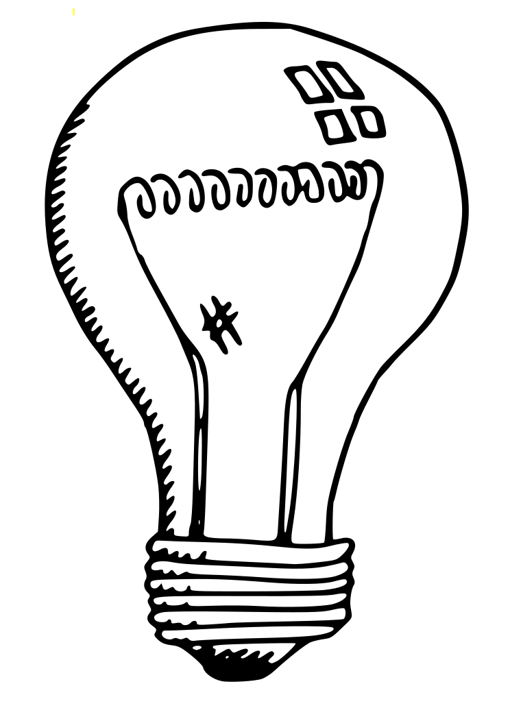
All electronic devices, from simple to complex, manipulate the flow of electrical current to achieve desired effects in the real world. Computers are no exception. When we write software, we indirectly manipulate electrical current at the physical level, in such a way that the underlying machine produces desired effects. To understand the process, we consider a simple light bulb. A light bulb can change two states between on and off with a switch, periodically: an off means number 0, and an on means 1.
However, one problem is that such a switch requires manual intervention from a human. What is required is an automatic switch based on the voltage level, as described above. To enable automatic switching of electrical signals, a device called a transistor was invented by William Shockley, John Bardeen and Walter Brattain. This invention started the whole computer industry.
At the core, a transistor is just a resistor whose values can vary based on an input voltage value.
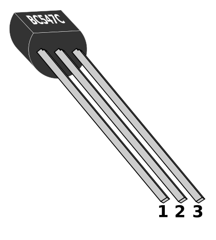
With this property, a transistor can be used as a current amplifier (more voltage, less resistance) or switch electrical signals off and on (block and unblock an electron flow) based on a voltage level. At 0 v, no current can pass through a transistor, thus it acts like a circuit with an open switch (light bulb off) because the resistor value is enough to block the electrical flow. Similarly, at +3.5 v, current can flow through a transistor because the resistor value is lessened, effectively enabling electron flow, thus acting like a circuit with a closed switch1.
A bit has two states: 0 and 1, which is the building block of all digital systems and software. Similar to a light bulb that can be turned on and off, bits are made out of this electrical stream from the power source: Bit 0 is represented with 0 v (no electron flow), and bit 1 is +3.5 v to +5 v (electron flow). A transistor implements a bit correctly, as it can regulate the electron flow based on voltage level.
2.1.1 MOSFET transistors
The invention of the classic transistor opened a whole new world of micro digital devices. Prior to the invention, vacuum tubes - which are just fancier light bulbs - were used to represent 0 and 1, and required a human to turn them on and off. MOSFET, or Metal-Oxide-Semiconductor Field-Effect Transistor, invented in 1959 by Dawon Kahng and Martin M. (John) Atalla at Bell Labs, is an improved version of classic transistors that is more suitable for digital devices, as it requires shorter switching time between two states 0 and 1, is more stable, consumes less power and is easier to produce.
There are also two types of MOSFETs analogous to two types of transistors: n-MOSFET and p-MOSFET. n-MOSFET and p-MOSFET are also called NMOS and PMOS transistors for short.
2.2 Beyond transistors: digital logic gates
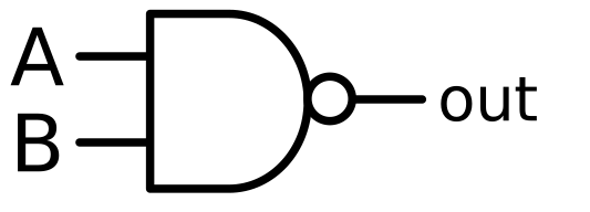
All digital devices are designed with logic gates. A logic gate is a device that implements a boolean function. Each logic gate includes a number of inputs and an output. All computer operations are built from the combinations of logic gates, which are just combinations of boolean functions.
2.2.1 The theory behind logic gates
Logic gates accept only binary inputs2 and produce binary outputs. In other words, logic gates are functions that transform binary values. Fortunately, a branch of math that deals exclusively with binary values already existed, called Boolean Algebra, developed in the 19th century by George Boole. With a sound mathematical theory as a foundation, logic gates were created. As logic gates implement Boolean functions, a set of Boolean functions is functionally complete if all other Boolean functions can be constructed from it. Later, Charles Sanders Peirce (during 1880-1881) proved that either the NOR or the NAND Boolean function alone is enough to create all other Boolean logic functions. Thus NOR and NAND gates are functionally complete (Peirce 1933). Gates are simply the implementations of Boolean logic functions, therefore NAND or NOR gate is enough to implement all other logic gates. The simplest gates a CMOS circuit can implement are inverters (NOT gates) and from the inverters, comes NAND gates. With NAND gates, we are confident to implement everything else. This is why the inventions of transistors, then CMOS circuit revolutionized the computer industry.
We should realize and appreciate how powerful the boolean functions available in all programming languages are.
2.2.2 Logic Gate implementation: CMOS circuit
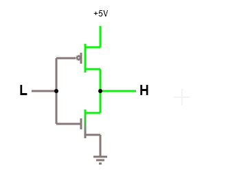
Underlying every logic gate is a circuit called CMOS - Complementary MOSFET. CMOS consists of two complementary transistors, NMOS and PMOS. The simplest CMOS circuit is an inverter or a NOT gate:
When input is low
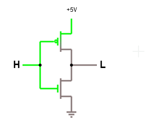
When input is high
Electron flows of an inverter. Input is on the left side and output on the right side. The upper component is a PMOS and the lower component is a NMOS, both connect to the input and output. (Source: Created with http://www.falstad.com/circuit/)
From NOT gate, a NAND gate can be created:
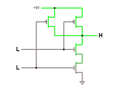
Input = 00, Output = 1
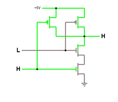
Input = 01, Output = 1
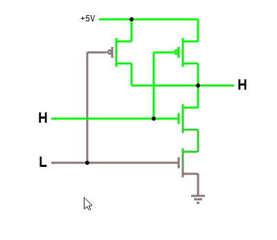
Input = 10, Output = 1
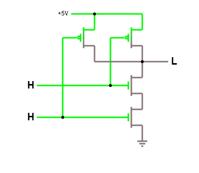
Input = 11, Output = 0
Electron flows of a NAND gate.
From NAND gate, we have all other gates. As demonstrated, such a
simple circuitry performs the logical operators in day-to-day
programming languages e.g. NOT operator ~ is executed
directly by an inverter circuit, and operator & is
executed by an AND circuit and so on. Code does not run on a magic black
box. In contrast, code execution is precise and transparent, often as
simple as running some hardwired circuit. When we write software, we
simply manipulate electrical current at the physical level to run
appropriate circuits to produce desired outcomes. However, this whole
process somehow does not relate to any thought involving electrical
current. That is the real magic and will be explained soon.
One interesting property of CMOS is that a k-input gate uses k PMOS and k NMOS transistors (Wakerly 1999). All logic gates are built by pairs of NMOS and PMOS transistors, and gates are the building blocks of all digital devices from simple to complex, including any computer. Thanks to this pattern, it is possible to separate between the actual physical circuit implementation and logical implementation. Digital designs are done by designing with logic gates and later “compiled” into physical circuits. In fact, later we will see that logic gates become a language that describes how circuits operate. Understanding how CMOS works is important to understand how a computer is designed, and as a consequence, how a computer works3.
Finally, an implemented circuit with its wires and transistors is stored physically in a package called a chip. A chip is a substrate that an integrated circuit is etched onto. However, a chip also refers to a completely packaged integrated circuit in consumer market. Depending on the context, it is understood differently.
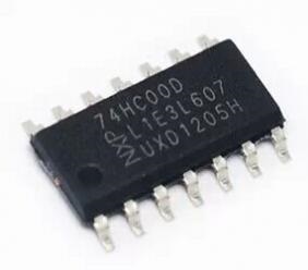
Example 2.1. 74HC00 is a chip with four 2-input NAND gates. The chip comes with 8 input pins and 4 output pins, 1 pin for connecting to a voltage source and 1 pin for connecting to the ground. This device is the physical implementation of NAND gates that we can physically touch and use. But instead of just a single gate, the chip comes with 4 gates that can be combined. Each combination enables a different logic function, effectively creating other logic gates. This feature is what makes the chip popular.
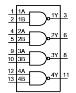
Logic diagram of 74HC00
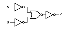
Logic diagram of one NAND gate
74HC00 logic diagrams (Source: 74HC00 datasheet, https://assets.nexperia.com/documents/data-sheet/74HC_HCT00.pdf)
Each of the gates above is just a simple NAND circuit with the electron flows, as demonstrated earlier. Yet, many of these NAND-gate chips combined can build a simple computer. Software, at the physical level, is just electron flows.
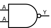
NOT gate
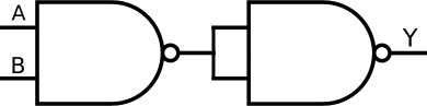
AND gate
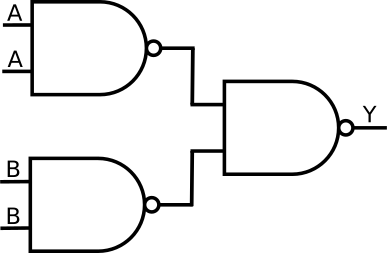
OR gate
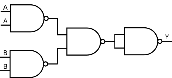
NOR gate
Gates built from NAND gates, each accepts 2 input signals and generate 1 output signal.
How can the above gates be created with 74HC00? It is simple: as every gate has 2 input pins and 1 output pin, we can write the output of 1 NAND gate to an input of another NAND gate, thus chaining NAND gates together to produce the diagrams as above.
2.3 Beyond Logic Gates: Machine Language
2.3.1 Machine language
Being built upon gates, as gates only accept a series of 0 and 1, a
hardware device only understands 0 and 1. However, a device only takes 0
and 1 in a systematic way. Machine language is a collection of
unique bit patterns that a device can identify and perform a
corresponding action. A machine instruction is a unique bit
pattern that a device can identify. In a computer system, a device with
its language is called a CPU - Central Processing
Unit, which controls all activities going inside a computer. For
example, in the x86 architecture, the pattern 00000000
tells a CPU to add two numbers, and 11110100 to halt a
computer. In the early days of computers, people had to write completely
in binary.
Why does such a bit pattern cause a device to do something? The reason is that underlying each instruction is a small circuit that implements the instruction. Similar to how a function/subroutine in a computer program is called by its name, a bit pattern is a name of a little function inside a CPU that got executed when the CPU finds one.
Note that CPU is not the only device with its language. CPU is just a name to indicate a hardware device that controls a computer system. A hardware device may not be a CPU but still has its language. A device with its own machine language is a programmable device, since a user can use the language to command the device to perform different actions. For example, a printer has its set of commands for instructing it how to print a page.
Example 2.2. A user can use 74HC00 chip without knowing its internals, but only the interface for using the device. First, we need to know its layout:
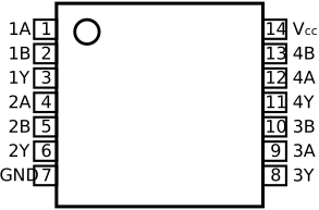
Then, the functionality of each pin:
| Symbol | Pin | Description |
|---|---|---|
| 1A to 4A | 1, 4, 9, 12 | data input |
| 1B to 4B | 2, 5, 10, 13 | data input |
| 1Y to 4Y | 3, 6, 8, 11 | data output |
| GND | 7 | ground (0 V) |
| Vcc | 14 | supply voltage |
Finally, how to use the pins:
| Output | ||
|---|---|---|
| nA | nB | nY |
| L | L | H |
| L | X | H |
| X | L | H |
| H | H | L |
The functional description provides a truth table with all possible pin inputs and outputs, which also describes the usage of all pins in the device. A user does not need to know the implementation, only such a table, to use the device. We can say that the truth table above is the machine language of the device. Since the device is digital, its language is a collection of binary strings:
The device has 8 input pins, and this means it accepts binary strings of 8 bits.
The device has 4 output pins, and this means it produces binary strings of 4 bits from the 8-bit inputs.
The input strings are what the device understands, and the output strings are what the device can speak. Together, they make the language of the device. Even though this device is simple, the language it can accept contains quite a lot of binary strings: . However, the number is a tiny fraction of a complex device like a CPU, with hundreds of pins.
When left as is, 74HC00 is simply a NAND device with two 4-bit inputs4.
| Input | Output | |||||||||||
|---|---|---|---|---|---|---|---|---|---|---|---|---|
| Pin | 1A |
1B |
2A |
2B |
3A |
3B |
4A |
4B |
1Y |
2Y |
3Y |
4Y |
| Value | 1 |
1 |
0 |
0 |
1 |
1 |
0 |
0 |
0 |
1 |
0 |
1 |
The inputs and outputs as visually presented:
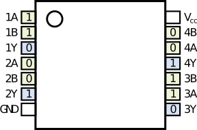
On the other hand, if an OR gate is implemented, we can only build a 2-input OR gate from 74HC00, as it requires 3 NAND gates: 2 input NAND gates and 1 output NAND gate. Each input NAND gate represents only a 1-bit input of the OR gate. In the following figure, the pins of each input NAND gates are always set to the same values (either both inputs are A or both inputs are B) to represent a single bit input for the final OR gate:
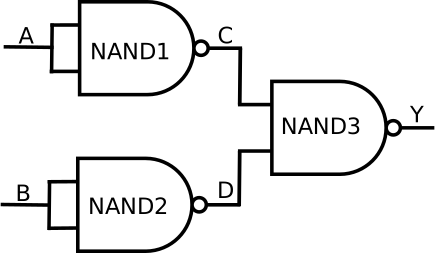
2-bit OR gate logic diagram, built from 3 NAND gates with 4 pins just for 2 bits of input.
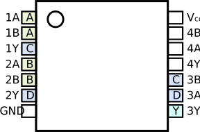
Pin 3A and 3B take the values from 1Y and 2Y.
2-bit OR gate implementation
| A | B | C | D | Y |
|---|---|---|---|---|
0 |
0 |
1 |
1 |
0 |
0 |
1 |
1 |
0 |
1 |
1 |
0 |
0 |
1 |
1 |
1 |
1 |
0 |
0 |
1 |
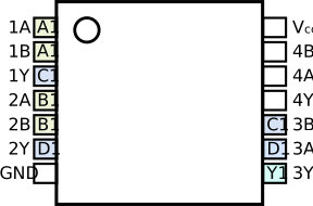
To implement a 4-bit OR gate, we need a total of four of 74HC00 chips configured as OR gates, packaged as a single chip as in the figure below.
2.3.2 Assembly Language
Assembly language is the symbolic representation of binary machine
code, by giving bit patterns mnemonic names. It was a vast improvement
over the days when programmers had to write 0 and 1. For example,
instead of writing 11110100, a programmer simply writes
hlt to stop a computer. Such an abstraction makes
instructions executed by a CPU easier to remember, and thus more
instructions could be memorized, less time spent looking up CPU manual
to find instructions in bit forms and as a result, code was written
faster.
Understanding assembly language is crucial for low-level programming domains, even to this day. The more instructions a programmer wants to understand, the deeper understanding of machine architecture is required.
Example 2.3. We can build a device with 2 assembly instructions:
or   <op1>, <op2>

nand <op1>, <op2>oraccepts two 4-bit operands. This corresponds to a 4-input OR gate device built from 4 74HC00 chips.nandaccepts two 4-bit operands. This corresponds to a single 74HC00 chip, left as is.
Essentially, the gates in example 2.2 implement the instructions. Up to this point, we only specify input and output and manually feed it to a device. That is, to perform an operation:
Pick a device by hands.
Manually put electrical signals into pins.
First, we want to automate the process of device selection. That is, we want to simply write assembly instruction and the device that implements the instruction is selected correctly. Solving this problem is easy:
Give each instruction an index in binary code, called operation code or opcode for short, and embed it as part of input. The value for each instruction is specified as in the following table.
Instruction-Opcode mapping. Instruction Binary Code nand00or01Each input now contains additional data at the beginning: an opcode. For example, the instruction:
nand 1100, 1100corresponds to the binary string:
0011001100. The first two bits00encode anandinstruction, as listed in the table above.Add another device to select a device, based on a binary code peculiar to an instruction.
Such a device is called a decoder, an important component in
a CPU that decides which circuit to use. In the above example, when
feeding 0011001100 to the
decoder, because the opcode is 00, data
are sent to NAND device for computing.
Finally, writing assembly code is just an easier way to write binary strings that a device can understand. When we write assembly code and save in a text file, a program called an assembler translates the text file into binary strings that a device can understand. So, how can an assembler exist in the first place? Assume this is the first assembler in the world, then it is written in binary code. In the next version, life is easier: the programmers write the assembler in the assembly code, then use the first version to compile itself. These binary strings are then stored in another device that later can be retrieved and sent to a decoder. A storage device is the device that stores machine instructions, which is an array of circuits for saving 0 and 1 states.
A decoder is built out of logic gates similar to other digital devices. However, a storage device can be anything that can store 0 and 1 and is retrievable. A storage device can be a magnetized device that uses magnetism to store information, or it can be made out of electrical circuits that can change and remember states when a voltage is applied. Regardless of the technology used, as long as the device can store data and is accessible to retrieve data, it suffices. Indeed, the modern devices are so complex that it is impossible and unnecessary to understand every implementation detail. Instead, we only need to learn the interfaces, e.g. the pins, that the devices expose.
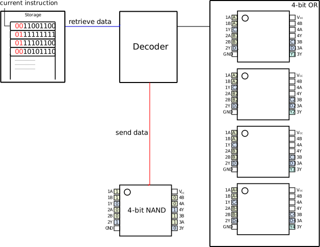
A computer essentially implements this process:
Fetch an instruction from a storage device.
Decode the instruction.
Execute the instruction.
Or in short, a fetch decode execute cycle. The above device is extremely rudimentary, but it already represents a computer with a fetch decode execute cycle. More instructions can be implemented by adding more devices and allocating more opcodes for the instructions, then update the decoder accordingly. The Apollo Guidance Computer, a digital computer produced for the Apollo space program from 1961 to 1972, was built entirely with NOR gates - the other choice to NAND gate for creating other logic gates. Similarly, if we keep improving our hypothetical device, it eventually becomes a full-fledged computer.
2.3.3 Programming Languages
Assembly language is a step up from writing 0 and 1. As time goes by,
people realized that many pieces of assembly code had repeating patterns
of usages. It would be nice if instead of writing all the repeating
blocks of code all over again in all places, we simply refer to such
blocks of code with easier to use text forms. For example, a block of
assembly code checks whether one variable is greater than another and if
so, execute a block of code, else execute another block of code; in C,
such block of assembly code is represented by an if
statement that is close to human language.
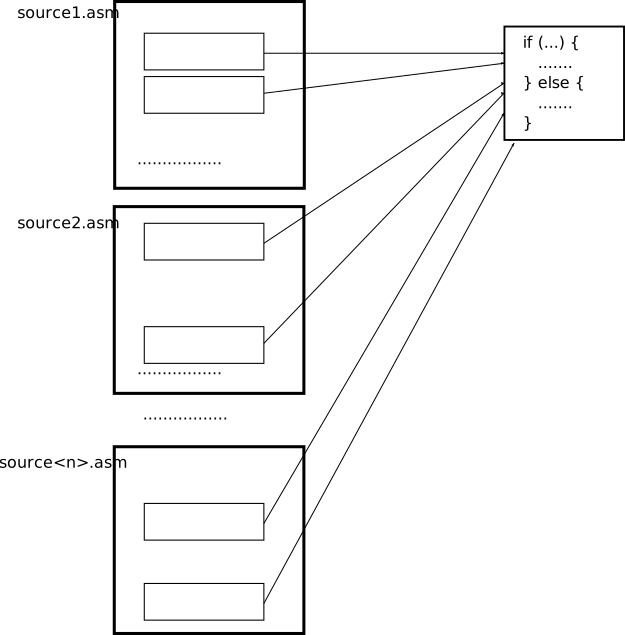
People created text forms to represent common blocks of assembly
code, such as the if syntax above, then write a program to
translate the text forms into assembly code. The program that translates
such text forms to machine code is called a compiler:
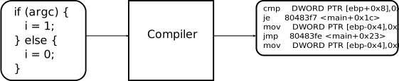
Any software logic a programming language can implement, hardware can also implement. The reverse is also true: any hardware logic that is implemented in a circuit can be reimplemented in a programming language. The simple reason is that programming languages, or assembly languages, or machine languages, or logic gates are just languages to express computations. It is impossible for software to implement something hardware is incapable of because programming language is just a simpler way to use the underlying hardware. At the end of the day, programming languages are translated to machine instructions that are valid to a CPU. Otherwise, code is not runnable, thus a useless software. In reverse, software can do everything hardware (that run the software) can, as programming languages are just an easier way to use the hardware.
In reality, even though all languages are equivalent in power, not all of them are capable of expressing each other’s programs effectively. Programming languages vary between two ends of a spectrum: high level and low level.
The higher level a programming language is, the more distant it becomes from the hardware. In some high-level programming languages, such as Python, a programmer cannot manipulate underlying hardware, despite being able to deliver the same computations as low-level programming languages. The reason is that high-level languages want to hide hardware details to free programmers from dealing with irrelevant details not related to current problem domains. Such convenience, however, is not free: it requires software to carry extra code for managing hardware details (e.g. memory) thus making the code run slower, and it makes hardware programming difficult or impossible. The more abstractions a programming language imposes, the more difficult it is for writing low-level software, such as hardware drivers or an operating system. This is the reason why C is usually a language of choice for writing an operating system, since C is just a thin wrapper of the underlying hardware, making it easy to understand how exactly a hardware device runs when executing a certain piece of C code.
Each programming language represents a way of thinking about programs. Higher-level programming languages help to focus on problem domains that are not related to hardware at all, and where programmer performance is more important than computer performance. Lower-level programming languages help to focus on the inner-working of a machine, thus are best suited for problem domains that are related to control hardware. That is why so many languages exist. Use the right tools for the right job to achieve the best results.
2.4 Abstraction
Abstraction is a technique for hiding complexity that is irrelevant to the problem in context. For example, imagine writing programs without any other layer except the lowest layer: circuits. Not only does a person need an in-depth understanding of how circuits work, it is also much more obscure to design a circuit because the designer must look at the raw circuits but think at a higher level, such as logic gates. It is a distracting process, as a designer must constantly translate the idea into circuits. It is better for a designer to simply think his high-level ideas straight, and later translate the ideas into circuits. Not only is it more efficient, but it is also more accurate as a designer can focus all his efforts into verifying the design with high-level thinking. When a new designer arrives, he can easily understand the high-level designs, thus can continue to develop or maintain existing systems.
2.4.1 Why abstraction works
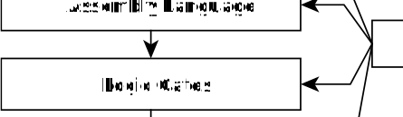
In all the layers, abstraction manifests itself:
Logic gates abstract away the details of CMOS.
Machine language abstracts away the details of logic gates.
Assembly language abstracts away the details of machine languages.
Programming language abstracts away the details of assembly languages.
We see repeating patterns of how lower-layers build upper-layers:
A lower layer has a recurring pattern. Then, this recurring pattern is taken out and a language is built on top of it.
A higher layer strips away layer-specific (non-recurring) details to focus on the recurring details.
The recurring details are given a new and simpler language than the languages of the lower layers.
What to realize is that every layer is just a more convenient language to describe the lower layer. Only after a description is fully created with the language of the higher layer, it is then implemented with the language of the lower layer.
CMOS layer has a recurring pattern that makes sure logic gates are reliably translated to CMOS circuits: a k-input gate uses k PMOS and k NMOS transistors (Wakerly 1999). Since digital devices use CMOS exclusively, a language arose to describe higher level ideas while hiding CMOS circuits: Logic Gates.
Logic Gates hides the language of circuits and focuses on how to implement primitive Boolean functions and combine them to create new functions. All logic gates receive input and generate output as binary numbers. Thanks to these recurring patterns, logic gates are hidden away for the new language: Assembly, which is a set of predefined binary patterns that cause the underlying gates to perform an action.
Soon, people realized that many recurring patterns arose from within Assembly language. Repeated blocks of Assembly code appear in Assembly source files that express the same or similar idea. There were many such ideas that can be reliably translated into Assembly code. Thus, the ideas were extracted for building into the high level programming languages that every programmer learns today.
Recurring patterns are the key to abstraction. Recurring patterns are why abstraction works. Without them, no language can be built, and thus no abstraction. Fortunately, humans have already developed a systematic discipline for studying patterns: Mathematics. As quoted from the British mathematician G. H. Hardy (Hardy 2005):
A mathematician, like a painter or a poet, is a maker of patterns. If his patterns are more permanent than theirs, it is because they are made with ideas.
Isn’t a mathematical formula a representation of a pattern? Doesn’t a variable represent values with the same properties given by constraints? Mathematics provides a formal system to identify and describe existing patterns in nature. For that reason, this system can certainly be applied in the digital world, which is just a subset of the real world. Mathematics can be used as a common language to help translation between layers easier, and help with the understanding of layers.
2.4.2 Why abstraction reduces complexity
Abstraction by building language certainly leverages productivity by stripping irrelevant details to a problem. Imagine writing programs without any other layer except the lowest layer: with circuits. This is how complexity emerges: when high-level ideas are expressed with lower-level language, as the example above demonstrated. Unfortunately, this is the case with software as programming languages at the moment are more emphasized on software rather than the problem domains. That is, without prior knowledge, code written in a language is unable to express itself the knowledge of its target domain. In other words, a language is expressive if its syntax is designed to express the problem domain it is trying to solve. That is, it expresses what it will do rather than how it will do it. Consider this example:
Example 2.4. Graphviz (http://www.graphviz.org/) is a visualization software
that provides a language, called dot, for describing
graphs:
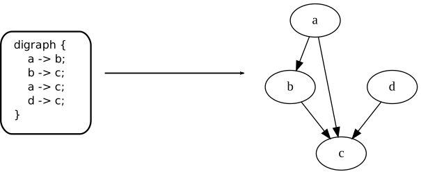
As can be seen, the code perfectly expresses itself how the graph is connected. Even a non-programmer can understand and use such language easily. An implementation in C would be more troublesome, and that’s assuming that the functions for drawing graphs are already available. To draw a line, in C we might write something like:
draw_line(a, b);However, it is still verbose compared with:
a -> b;Also, a and b must be defined in C,
compared to the implicit nodes in the dot language.
However, if we do not factor in the verbosity, then C still has a
limitation: it cannot change its syntax to suit the problem domain. A
domain-specific language might even be more verbose, but it makes a
domain more understandable. If a problem domain must be expressed in C,
then it is constrained by the syntax of C. Since C is not a language
specialized for a problem domain, but a general-purpose
programming language, the domain knowledge is buried within the
implementation details. As a result, a C programmer is needed to
decipher and extract the domain knowledge out. If the domain knowledge
cannot be extracted, then the software cannot be further developed.
Example 2.5. Linux is full of applications
controlled by many domain-specific languages and are placed in
/etc directory, such as a web server. Instead of
reprogramming the software, a domain-specific language is made for
it.
In general, code that can express a problem domain must be understandable by a domain expert. Even within the software domain, building a language out of repeated programming patterns is useful. It helps people be aware of the existence of such patterns in code and thus makes software easier to maintain, as software structure is visible as a language. Only a programming language that is capable of morphing itself to suit a problem domain can achieve that goal. Such language is called a programmable programming language. Unfortunately, this approach of turning software structure visible is not favored among programmers, as a new language must be made out of it along with new toolchain to support it. Thus, software structure and domain knowledge are buried within code written in the syntax of a general-purpose language, and if a programmer is not familiar or even aware of the existence of a code pattern, then it is hopeless to understand the code. A prime example is reading C code that controls hardware, e.g. an operating system: if a programmer knows absolutely nothing about hardware, then it is impossible to read and write operating system code in C, even if he could have 20 years of writing application C code.
With abstraction, a software engineer can also understand the inner workings of a device without specialized knowledge of the physical circuit design. This also enables them to write code that controls the device. The separation between logical and physical implementation also entails that gate designs can be reused even when the underlying technologies change. For example, in some distant future biological computer could be a reality, and gates might not be implemented as CMOS but some kind of biological cells e.g. as living cells; in either technology: electrical or biological, as long as logic gates are physically realized, the same computer design could be implemented.
2.5 Exercises
Exercise 2.1. Open the circuit simulator at http://www.falstad.com/circuit/ and build the inverter of the figure above with one PMOS and one NMOS transistor (both are in the Active Components menu). Toggle the input and watch which of the two transistors conducts. Then add a second pair to turn it into the NAND gate, and try the four input combinations. Explain, in terms of which transistors conduct, why the output is pulled to ground only when both inputs are high.
Exercise 2.2. Using only 2-input NAND gates, on paper or in the simulator, build an XOR gate. Count the gates. Then, with the pin table of example 2.2, write down how you would wire a single 74HC00 to obtain it: which output pin feeds which input pin, and where the two inputs and the output of your XOR end up. Check your wiring by filling the truth table pin by pin, as the chapter did for the OR gate.
Exercise 2.3. The chapter says that
11110100 tells an x86 CPU to halt and that
00000000 tells it to add. Check it. Put the two lines
hlt and add al, al in a file
two.asm, assemble it with
nasm -f bin two.asm -o two.bin, and look at the bytes with
xxd two.bin. Then open Intel SDM Volume 2A, find the pages
of the HLT and ADD instructions, and read
their Opcode column. Explain why hlt takes one
byte and add takes two, and what the second byte says.
Chapter 4 explains the encoding in detail.
Exercise 2.4. Take hello.c from chapter
0 and produce its three lower layers:
gcc $BOOKFLAGS -S hello.c -o hello.s gives the assembly,
gcc $BOOKFLAGS -c hello.c -o hello.o gives the machine
code, and objdump -M intel -d hello.o shows both side by
side. Find the statement return 0; in each of the three
forms and write down how many characters, how many instructions and how
many bytes it takes. Do not try to understand the rest yet; the point is
to see the layers of this chapter on a real program. Chapter 4 reads
this output line by line.
Exercise 2.5. Extend the two-instruction machine of
example 2.3 with a third instruction, not, with opcode
10, built from one NAND gate whose two inputs are tied
together. Write the truth table of the decoder: two opcode bits in,
three select lines out, one per device. Then feed it the opcode
11, which you have not defined, and decide what your
decoder does. A real CPU has the same problem, and raises an invalid
opcode exception; chapter 11 shows the x86 version of it.
2.6 Check your understanding
Why is a NAND gate alone enough to build any digital device? What is the name of this property?
What is the difference between a transistor and a logic gate? Which of the two does a digital designer think in, and why?
The chapter repeats that “a k-input gate uses k PMOS and k NMOS transistors”. What does this regularity make possible for the designer?
Why does the user of a 74HC00 need its truth table, when the internals of the chip are known and shown in the chapter? What does the user lose by ignoring the internals?
What is the job of the decoder in example 2.3, and what would be missing from the machine without it?
In what sense is an opcode “the name of a function inside the CPU”? What is the body of that function?
Why does the book say that every layer is a more convenient language for describing the layer below, and why are recurring patterns necessary for a new layer to exist?
Python can express the same computations as C. Why is C, and not Python, the language of choice for an operating system?
If you want a deeper explanation of transistors, e.g. how electrons move, you should look at the video “How semiconductors work” on YouTube, by Ben Eater.↩︎
Input that is either a 0 or 1.↩︎
Again, if you want to understand how logic gates make a computer, consider the suggested courses on Coursera and Edx earlier.↩︎
Or simply 4-bit NAND gate, as it can only accept 4 bits of input at the maximum.↩︎