11 Interrupts
The kernel of chapter 10, Talking to devices: the serial port and the VGA text console, can talk, but it cannot listen. Its serial driver polls: before writing a byte it reads the line status register in a loop until the transmitter is empty. Polling works when the kernel has nothing else to do, which is why we could get away with it, but it does not scale. A keyboard produces a byte every few hundred milliseconds at best; a kernel that checked the keyboard port in a loop would spend 99.99% of its time asking “anything yet?” and could do nothing else meanwhile. Worse, some events cannot be polled at all: when a program divides by zero, the CPU must stop it right now, in the middle of the instruction, not at the next convenient moment.
An interrupt turns the relationship around. Instead of the
kernel asking the device, the device tells the CPU, and the CPU suspends
whatever it is running, calls a function of the kernel, and resumes the
suspended code when the function returns. The same mechanism serves the
CPU itself to report errors, in which case it is called an
exception, and serves programs to call into the kernel on
purpose with the int instruction, which is how system calls
will work in chapter 13, Processes. Everything that follows in this book
is built on it: the scheduler of chapter 13 runs on the timer interrupt,
paging in chapter 12 relies on the page-fault exception, and user
programs reach the kernel through a software interrupt.
In this chapter the kernel gains four things: an Interrupt Descriptor Table so that the CPU knows where its handlers are, a handler for each of the 32 CPU exceptions, a driver for the 8259A interrupt controller that delivers hardware interrupts, and two devices that use it, the timer and the keyboard. At the end the kernel prints the time every second and echoes what we type, without ever polling.
Running this chapter’s code
The code is in code/chapter11/os: the chapter 10 kernel
plus the files listed in the next section. From the root of the
repository, in the chapter 0 container:
$ docker run --rm --user "$(id -u):$(id -g)" --security-opt seccomp=unconfined -v "$PWD":/work -w /work/code/chapter11/os os01 make testmake builds the kernel, the bootloader and
build/disk.img. make qemu boots the image
stopped at its first instruction, with the serial port on the terminal
(-serial stdio) and a gdb stub on port 26000;
make gdb in a second terminal connects, loads the symbols
and stops at kmain, so that b isr_dispatch
followed by c lands you in the kernel’s first interrupt.
make test runs tools/serial-test.sh, which
boots the image headless with the serial port captured to a file, waits
up to 15 seconds for the string timer: 3 seconds, the third
line printed from the timer interrupt, then prints everything the kernel
wrote. The keyboard cannot be tested that way; the section “Typing
without a keyboard” shows how to inject key presses from the QEMU
monitor.
11.1 Interrupts and exceptions on x86
The reading guide for this chapter is Intel SDM Volume 3A, chapter 7 “Interrupt and Exception Handling”. It is one of the better-written chapters of the manual, and our code follows its order. The sections you need, and what to look for in each:
Sections 7.1 and 7.2: an interrupt is identified by a vector, a number from 0 to 255. The CPU uses the vector as an index into a table of 256 entries, the IDT, and jumps to the handler recorded there.
Section 7.3 “Sources of Interrupts” and 7.4 “Sources of Exceptions”: interrupts come from outside the CPU (a device raising a pin, through an interrupt controller) or from the
int ninstruction; exceptions come from the CPU detecting an error while executing an instruction. Table 7-1 “Protected-Mode Exceptions and Interrupts” is the table you will return to most often: it lists the 32 vectors that Intel reserves, with their mnemonic (#DE,#GP,#PF…), their type and whether they push an error code. Vectors 32 to 255 are user defined, meaning the operating system decides what they mean.Section 7.5 “Exception Classifications” separates faults, traps and aborts. This is the section that explains a bug you would otherwise spend a day on, and we come back to it below.
Section 7.8 “Enabling and Disabling Interrupts”: the
IFflag inEFLAGS, set bystiand cleared bycli, controls whether the CPU listens to maskable hardware interrupts. Exceptions andint nignore it.Sections 7.10 and 7.11: the IDT and its gate descriptors. Figure 7-2 “IDT Gate Descriptors” is the layout we translate into a C structure.
Section 7.12 “Exception and Interrupt Handling”: what the CPU does between the event and the first instruction of the handler. Figure 7-4 “Stack Usage on Transfers to Interrupt and Exception-Handling Routines” shows what it pushes. Section 7.12.1.3 explains the one difference between an interrupt gate and a trap gate: the former clears
IFon entry, the latter does not.Section 7.13 “Error Code”: the format of the extra word that some exceptions push.
Section 7.15 “Exception and Interrupt Reference”: one page per exception, with the exact conditions that raise it. Read the pages for
#DE,#BP,#GPand#DFnow;#PFis for chapter 12.
Everything the code in this chapter does is a translation of those sections, and the comments in the source give the section number next to each structure.
11.1.1 What the CPU does on an interrupt
When an interrupt with vector n arrives, the CPU, in protected mode:
- reads entry n of the IDT, an 8-byte gate descriptor that contains a code segment selector and an offset, in other words the address of the handler, and a few attribute bits;
- if the handler runs at a more privileged level than the interrupted code, switches to the kernel stack (chapter 13; for now everything is ring 0 and the stack does not change);
- pushes
EFLAGS,CSandEIPon the stack, in that order, so thatiretcan later come back; - for the exceptions marked in table 7-1, pushes an error code;
- if the gate is an interrupt gate, clears
IFso that another hardware interrupt does not interrupt the handler; - jumps to the handler.
The handler ends with iret, which pops EIP,
CS and EFLAGS and so restores the interrupted
code, including its IF. Note what the CPU does not
do: it does not save EAX, ECX, or any general
register, it does not tell the handler which vector was used, and it
does not pop the error code. All three are the handler’s problem, and
they dictate the shape of the assembly code in this chapter.
11.1.2 Faults, traps and aborts
Section 7.5 classifies the exceptions by what the saved
EIP points to:
A fault is reported before the instruction completes, and the saved
EIPpoints to the faulting instruction. If the handler fixes the cause and returns, the instruction runs again. This is what makes demand paging possible: a page fault handler maps the missing page and returns, and the load that faulted simply executes a second time. It also means that a handler that returns without fixing the cause gets the same fault again, immediately, forever. Division by zero (#DE) and general protection (#GP) are faults.A trap is reported after the instruction completes, and the saved
EIPpoints to the next instruction. Returning continues the program.int 3, the breakpoint instruction, is a trap: a debugger plants it, gets control, and lets the program continue from the instruction after it.An abort reports a state so broken that restarting is not possible; the double fault (
#DF) and machine check are aborts.
Our kernel uses both rules: the breakpoint handler just returns,
which works because #BP is a trap, and every other
exception stops the machine after printing the registers, because
returning from a fault without fixing it would loop. Later chapters
replace the halt by something smarter for the faults they expect (a page
fault in chapter 12, a bad system call in chapter 13); the rule stays
the same.
11.1.3 Exceptions, the PIC and the collision of vectors
Hardware interrupts reach the CPU through an interrupt
controller, which on the PC is a pair of Intel 8259A chips. The
controller is told which vector to use for each of its input lines, and
the BIOS programs it to put the timer (its line 0) on vector 8, the
keyboard (line 1) on vector 9, and so on up to vector 15. That choice
was made in 1981 for the 8088, which had no protected mode and only
reserved vectors 0 to 4. On a 386 and later, vectors 8 to 15 are
#DF, #TS, #NP, #SS,
#GP and #PF: with the BIOS setting, a timer
tick would look exactly like a double fault. The first thing a
protected-mode kernel does with the controller is therefore to move its
vectors somewhere above 31; we use 32 to 47, which is where every hobby
and most production kernels put them.
11.2 The IDT in code
What the chapter adds to the kernel of chapter 10 is the following,
all under code/chapter11/os/os/:
$ diff -rq ../../chapter10/os/os os
Only in os: idt.c
Only in os: idt.h
Only in os: isr.c
Only in os: isr.h
Only in os: isr_stubs.asm
Files ../../chapter10/os/os/kernel.c and os/kernel.c differ
Only in os: keyboard.c
Only in os: keyboard.h
Only in os: pic.c
Only in os: pic.h
Only in os: pit.c
Only in os: pit.h
We start from the table.
11.2.1 The gate descriptor
Figure 7-2 of Volume 3A gives three gate layouts; we only need the interrupt gate and, for an exercise, the trap gate. Both are 8 bytes:
idt.h
#ifndef IDT_H
#define IDT_H

#include <stdint.h>

/* One 8-byte gate descriptor, Intel SDM Vol. 3A, section 7.11 "IDT
   Descriptors", Figure 7-2.  Like a GDT entry, the 32-bit handler address is
   split in two for 286 compatibility. */
struct idt_entry {
    uint16_t offset_low;    /* handler address bits 15:0 */
    uint16_t selector;      /* code segment selector of the handler */
    uint8_t  zero;          /* reserved, must be 0 */
    uint8_t  type_attr;     /* P | DPL(2) | 0 | gate type(4) */
    uint16_t offset_high;   /* handler address bits 31:16 */
} __attribute__((packed));

/* Operand of LIDT, Intel SDM Vol. 3A, section 2.4.3 "Interrupt Descriptor
   Table Register (IDTR)". */
struct idt_ptr {
    uint16_t limit;
    uint32_t base;
} __attribute__((packed));

/* type_attr values.  0xE = 32-bit interrupt gate: the processor clears IF on
   entry so the handler is not interrupted; 0xF would be a trap gate, which
   leaves IF alone (Intel SDM Vol. 3A, section 7.12.1.3).  Bit 7 = present,
   bits 5-6 = DPL, the privilege a caller of INT n needs. */
#define IDT_INTERRUPT_GATE_RING0 0x8E
#define IDT_INTERRUPT_GATE_RING3 0xEE

#define IDT_ENTRIES 256

void idt_set_gate(uint8_t vector, uint32_t handler, uint16_t selector,
                  uint8_t type_attr);
void idt_init(void);

#endif
Compare with the segment descriptor of chapter 9, Protected mode and
x86 descriptors: the same 8 bytes, the same historical split of a 32-bit
field across two halves, and the same
__attribute__((packed)) to stop gcc from
inserting padding. The offset is the address of the handler
inside the segment named by selector; with our flat GDT the
selector is always GDT_KERNEL_CODE, 0x08, and
the offset is simply the address. The type_attr byte packs
four things:
| bits | field | value for us |
|---|---|---|
| 7 | P, present | 1 |
| 6-5 | DPL | 0 (3 for a gate that int n may use from user mode,
chapter 13) |
| 4 | always 0 for a gate | 0 |
| 3-0 | type: 1110 32-bit interrupt gate, 1111
32-bit trap gate |
1110 |
which gives 0x8E for our handlers and 0xEE
for the system call gate of chapter 13. The DPL of a gate is
not the privilege level the handler runs at (that comes from
the selector); it is the privilege level a program needs to be allowed
to execute int n for this vector. With DPL 0,
int 0x20 from a user program raises #GP
instead of faking a timer tick. Hardware interrupts and exceptions
ignore the gate’s DPL.
struct idt_ptr is the 6-byte operand of the
lidt instruction, the twin of the lgdt operand
of chapter 9: a 16-bit limit, which is the size of the table minus one,
and a 32-bit base address.
11.2.2 Filling the table
idt.c
/* idt.c -- the Interrupt Descriptor Table.
 *
 * The IDT maps each of the 256 interrupt vectors to a handler address
 * (Intel SDM Vol. 3A, section 7.10 "Interrupt Descriptor Table (IDT)").
 * Vectors 0-31 are architecturally defined exceptions, 32-255 are free for
 * the OS; the PIC is programmed (pic.c) to deliver hardware interrupts on
 * 32-47.  The handlers themselves are the assembly stubs in isr_stubs.asm.
 */
#include "idt.h"
#include "gdt.h"
#include "string.h"

/* Addresses of isr0..isr47 in isr_stubs.asm, in order. */
extern void (*isr_stub_table[48])(void);

static struct idt_entry idt[IDT_ENTRIES];
static struct idt_ptr   idt_pointer;

void idt_set_gate(uint8_t vector, uint32_t handler, uint16_t selector,
                  uint8_t type_attr)
{
    idt[vector].offset_low  = handler & 0xFFFF;
    idt[vector].offset_high = (handler >> 16) & 0xFFFF;
    idt[vector].selector    = selector;
    idt[vector].zero        = 0;
    idt[vector].type_attr   = type_attr;
}

void idt_init(void)
{
    int i;

    /* A gate with P=0 raises #NP (vector 11) if the vector is ever used,
       which is better than jumping to address 0. */
    memset(idt, 0, sizeof(idt));

    for (i = 0; i < 48; i++)
        idt_set_gate(i, (uint32_t)isr_stub_table[i], GDT_KERNEL_CODE,
                     IDT_INTERRUPT_GATE_RING0);

    idt_pointer.limit = sizeof(idt) - 1;
    idt_pointer.base  = (uint32_t)&idt;
    asm volatile("lidt %0" : : "m"(idt_pointer));
}
The table has 256 entries, 2 KiB, and lives in .bss.
Only the first 48 are filled: 32 exceptions and 16 hardware interrupt
lines. The other 208 are left zero, and a zero entry has P = 0, so an
interrupt on one of those vectors raises #NP, “Segment Not
Present”, with an error code that names the vector. This is a deliberate
safety net: when the kernel of chapter 13 installs vector
0x80 for system calls, a typo that sends
int 0x81 is reported instead of silently jumping to address
0.
The lidt line is GCC inline assembly with a memory
operand: "m"(idt_pointer) tells the compiler to pass the
address of the structure, and lidt reads 6 bytes
from it. Here is what gcc made of the whole function, from
objdump -d -M intel build/os/os; look at the last four
instructions:
000106d7 <idt_init>:
   106d7:   55                      push   ebp
   106d8:   89 e5                   mov    ebp,esp
   106da:   83 ec 18                sub    esp,0x18
   106dd:   83 ec 04                sub    esp,0x4
   106e0:   68 00 08 00 00          push   0x800
   106e5:   6a 00                   push   0x0
   106e7:   68 c0 19 01 00          push   0x119c0
   106ec:   e8 f8 09 00 00          call   110e9 <memset>
   106f1:   83 c4 10                add    esp,0x10
   106f4:   c7 45 f4 00 00 00 00    mov    DWORD PTR [ebp-0xc],0x0
   106fb:   eb 27                   jmp    10724 <idt_init+0x4d>
   106fd:   8b 45 f4                mov    eax,DWORD PTR [ebp-0xc]
   10700:   8b 04 85 c0 13 01 00    mov    eax,DWORD PTR [eax*4+0x113c0]
   10707:   89 c2                   mov    edx,eax
   10709:   8b 45 f4                mov    eax,DWORD PTR [ebp-0xc]
   1070c:   0f b6 c0                movzx  eax,al
   1070f:   68 8e 00 00 00          push   0x8e
   10714:   6a 08                   push   0x8
   10716:   52                      push   edx
   10717:   50                      push   eax
   10718:   e8 50 ff ff ff          call   1066d <idt_set_gate>
   1071d:   83 c4 10                add    esp,0x10
   10720:   83 45 f4 01             add    DWORD PTR [ebp-0xc],0x1
   10724:   83 7d f4 2f             cmp    DWORD PTR [ebp-0xc],0x2f
   10728:   7e d3                   jle    106fd <idt_init+0x26>
   1072a:   66 c7 05 c0 21 01 00    mov    WORD PTR ds:0x121c0,0x7ff
   10731:   ff 07
   10733:   b8 c0 19 01 00          mov    eax,0x119c0
   10738:   a3 c2 21 01 00          mov    ds:0x121c2,eax
   1073d:   0f 01 1d c0 21 01 00    lidtd  ds:0x121c0
   10744:   90                      nop
   10745:   c9                      leave
   10746:   c3                      ret
The table idt is at 0x119c0 (the first
argument of memset, 2048 bytes long),
idt_pointer is at 0x121c0, and the two stores
before lidtd write the limit 0x7ff and the
base 0x119c0 into it. The d in
lidtd is objdump telling us this is the 32-bit
form of the instruction, with a 32-bit base. The loop reads the stub
addresses from the table at 0x113c0, which is
isr_stub_table in .rodata; we see where that
table comes from next.
11.2.3 Why the handlers are in assembly
An IDT entry holds the address of a function, so why not put the
address of a C function there? Because of the three things the CPU does
not do, listed above. A C function compiled by gcc assumes
the standard calling convention: it may clobber EAX,
ECX and EDX without saving them, and it
returns with ret, which pops a 4-byte return address. An
interrupt handler must preserve every register, because the
interrupted code was not expecting a call, and it must return with
iret, which pops 12 bytes. Also, half the exceptions leave
an error code on the stack that iret will not remove, and
nobody tells the handler which vector fired. All of this is a few lines
of assembly per vector, and it is the only assembly this chapter
needs.
isr_stubs.asm
;******************************************************************************
; isr_stubs.asm -- entry points for exceptions 0-31 and hardware interrupts 0-15.
;
; The processor only pushes EFLAGS, CS, EIP and (for some exceptions) an
; error code before jumping to the handler in the IDT (Intel SDM Vol. 3A,
; section 7.12.1, Figure 7-4).  It does not tell the handler which vector
; fired, so every vector gets its own tiny stub that pushes the vector
; number, then all stubs share isr_common, which saves the remaining
; registers and calls the C function isr_dispatch(struct registers *).
;
; Exceptions that push an error code (Intel SDM Vol. 3A, Table 7-1):
;   8 #DF, 10 #TS, 11 #NP, 12 #SS, 13 #GP, 14 #PF, 17 #AC, 21 #CP.
; For the others the stub pushes a 0 so that the stack layout, and hence
; struct registers in isr.h, is the same for every vector.
;******************************************************************************
bits 32
section .text
extern isr_dispatch

; Each macro expands to, for example (ISR_NOERRCODE 3):
;     global isr3
;     isr3:  push dword 0      ; fake error code
;            push dword 3      ; vector number
;            jmp  isr_common
%macro ISR_NOERRCODE 1
global isr%1
isr%1:
    push    dword 0
    push    dword %1
    jmp     isr_common
%endmacro

%macro ISR_ERRCODE 1
global isr%1
isr%1:
    push    dword %1
    jmp     isr_common
%endmacro
Two NASM macros generate the per-vector stubs.
%macro ISR_NOERRCODE 1 defines a macro with one parameter;
%1 is replaced by the argument. The only job of a stub is
to make the stack look the same whatever the vector: vectors that do not
push an error code push a fake 0 first, then every stub
pushes its own vector number and jumps to the shared code. This is the
error-code normalization that lets a single C structure
describe the stack for all 48 vectors. The macros are then invoked once
per vector, with the mnemonics of table 7-1 as comments:
ISR_NOERRCODE 0         ; #DE divide error
ISR_NOERRCODE 1         ; #DB debug
ISR_NOERRCODE 2         ;     NMI
ISR_NOERRCODE 3         ; #BP breakpoint (INT 3)
ISR_NOERRCODE 4         ; #OF overflow
ISR_NOERRCODE 5         ; #BR bound range exceeded
ISR_NOERRCODE 6         ; #UD invalid opcode
ISR_NOERRCODE 7         ; #NM device not available
ISR_ERRCODE   8         ; #DF double fault
ISR_NOERRCODE 9         ;     coprocessor segment overrun (386 only)
ISR_ERRCODE   10        ; #TS invalid TSS
ISR_ERRCODE   11        ; #NP segment not present
ISR_ERRCODE   12        ; #SS stack-segment fault
ISR_ERRCODE   13        ; #GP general protection
ISR_ERRCODE   14        ; #PF page fault
ISR_NOERRCODE 15        ;     reserved
ISR_NOERRCODE 16        ; #MF x87 floating-point error
ISR_ERRCODE   17        ; #AC alignment check
ISR_NOERRCODE 18        ; #MC machine check
ISR_NOERRCODE 19        ; #XM SIMD floating-point
ISR_NOERRCODE 20        ; #VE virtualization
ISR_ERRCODE   21        ; #CP control protection
ISR_NOERRCODE 22        ;     reserved
ISR_NOERRCODE 23
ISR_NOERRCODE 24
ISR_NOERRCODE 25
ISR_NOERRCODE 26
ISR_NOERRCODE 27
ISR_NOERRCODE 28
ISR_NOERRCODE 29
ISR_NOERRCODE 30
ISR_NOERRCODE 31

; Hardware interrupts: IRQ n arrives on vector 32 + n once the PIC has been
; remapped (pic.c).  They never carry an error code.
ISR_NOERRCODE 32        ; IRQ 0  timer
ISR_NOERRCODE 33        ; IRQ 1  keyboard
ISR_NOERRCODE 34        ; IRQ 2  cascade (never raised: the slave PIC uses it)
ISR_NOERRCODE 35        ; IRQ 3  COM2
ISR_NOERRCODE 36        ; IRQ 4  COM1
ISR_NOERRCODE 37        ; IRQ 5
ISR_NOERRCODE 38        ; IRQ 6  floppy
ISR_NOERRCODE 39        ; IRQ 7  LPT1 / spurious
ISR_NOERRCODE 40        ; IRQ 8  real-time clock
ISR_NOERRCODE 41        ; IRQ 9
ISR_NOERRCODE 42        ; IRQ 10
ISR_NOERRCODE 43        ; IRQ 11
ISR_NOERRCODE 44        ; IRQ 12 PS/2 mouse
ISR_NOERRCODE 45        ; IRQ 13 FPU
ISR_NOERRCODE 46        ; IRQ 14 primary ATA
ISR_NOERRCODE 47        ; IRQ 15 secondary ATA
Here are two expanded stubs in the linked kernel, one of each kind:
0001013b <isr3>:
   1013b:   6a 00                   push   0x0
   1013d:   6a 03                   push   0x3
   1013f:   e9 3a 01 00 00          jmp    1027e <isr_common>

00010168 <isr8>:
   10168:   6a 08                   push   0x8
   1016a:   e9 0f 01 00 00          jmp    1027e <isr_common>
Nine bytes for a vector without error code, seven with. The
double-fault stub does not push a fake 0 because the CPU
already pushed a real error code (always 0 for #DF, but it
is there and must be accounted for).
11.2.4 The common stub and
struct registers
; Common part.  On entry the stack holds (top first):
;     vector number, error code, EIP, CS, EFLAGS [, ESP, SS if from ring 3]
isr_common:
    pusha                       ; EAX, ECX, EDX, EBX, ESP, EBP, ESI, EDI
    push    ds                  ; 32-bit push: 4 bytes each, matching
    push    es                  ; the uint32_t fields in struct registers
    push    fs
    push    gs

    ; The interrupted code may have had any data segment loaded (in later
    ; chapters, a user-mode one).  Switch to the kernel's.
    mov     ax, 0x10            ; GDT_KERNEL_DATA
    mov     ds, ax
    mov     es, ax
    mov     fs, ax
    mov     gs, ax

    push    esp                 ; struct registers *regs = current ESP
    call    isr_dispatch
    add     esp, 4              ; drop the argument

    pop     gs
    pop     fs
    pop     es
    pop     ds
    popa
    add     esp, 8              ; drop vector number and error code
    iret                        ; pops EIP, CS, EFLAGS (and ESP, SS if needed)

; Table of the 48 stub addresses, used by idt_init() to fill the IDT.
; %rep is a NASM loop: it emits "dd isr0", "dd isr1", ... "dd isr47".
section .rodata
global isr_stub_table
isr_stub_table:
%assign i 0
%rep 48
    dd isr%+i
%assign i i+1
%endrep
isr_common finishes building the picture of the
interrupted CPU on the stack, then hands the C code a pointer to it.
pusha pushes the eight general registers in the fixed order
EAX, ECX, EDX, EBX, ESP, EBP, ESI, EDI (Volume 2B,
“PUSHA/PUSHAD”), and the four pushes after it save the data segment
registers. Then the stub loads the kernel data selector into those
registers; in this chapter they already hold 0x10, but in
chapter 13 the interrupted code may be a user program with its own
selectors, and the C handler needs the kernel’s. push esp
passes the current stack pointer as the single argument of
isr_dispatch, and the second half of the function undoes
everything in reverse order. The add esp, 8 discards the
vector number and the error code, which iret knows nothing
about: forget it and iret would load EIP from
the error-code slot.
The isr_stub_table at the end is the array that
idt_init walks. %rep 48 with
%assign is a NASM compile-time loop; isr%+i
concatenates isr with the value of i. The loop
in idt_init read it at 0x113c0, in
.rodata; the bytes there are 20 01 01 00
(isr0 at 0x10120), 29 01 01 00
(isr1, nine bytes further), and so on.
Now the C side of the contract:
isr.h
#ifndef ISR_H
#define ISR_H

#include <stdint.h>

/* What the stack looks like when isr_dispatch() runs; the common stub in
   isr_stubs.asm builds it, so the field order here MUST match the push order
   there, read bottom-up.  Intel SDM Vol. 3A, section 7.12.1 "Exception- or
   Interrupt-Handler Procedures", Figure 7-4 shows the part the CPU pushes. */
struct registers {
    uint32_t gs, fs, es, ds;                /* pushed last by isr_common */
    uint32_t edi, esi, ebp, esp_dummy;      /* PUSHA: esp_dummy is ESP before PUSHA */
    uint32_t ebx, edx, ecx, eax;
    uint32_t int_no;                        /* pushed by the per-vector stub */
    uint32_t err_code;                      /* pushed by the CPU, or 0 by the stub */
    uint32_t eip, cs, eflags;               /* pushed by the CPU */
    uint32_t user_esp, ss;                  /* pushed by the CPU only when the
                                               interrupt came from ring 3 */
};

/* A C handler for one vector.  It may read and modify the saved registers;
   returning resumes whatever was interrupted. */
typedef void (*isr_handler_t)(struct registers *regs);

/* First vector the PIC delivers IRQ 0 on (set up in pic.c). */
#define IRQ_BASE 0x20

void isr_register_handler(uint8_t vector, isr_handler_t handler);
void isr_dispatch(struct registers *regs);

#endif
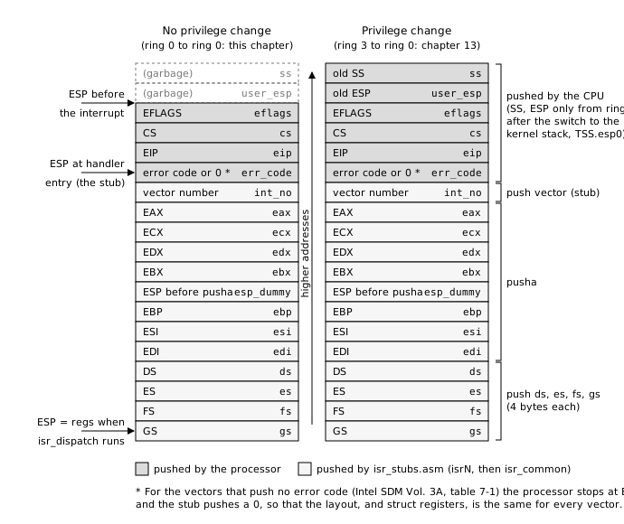
The structure is the stack, read from the lowest address up, so it lists the pushes in reverse order. Let us check it line by line against the pushes, starting from what the CPU did:
- The CPU pushed
EFLAGS,CS,EIP(and before themSSandESPwhen coming from ring 3). Pushing goes downwards in memory, so in memoryEIPis lowest, thenCS, thenEFLAGS:eip, cs, eflags, user_esp, ss. The last two fields only exist when the interrupt came from a less privileged level; for a ring-0 interrupt they overlap whatever was on the stack before, and must not be read. In this chapter they always hold garbage. - The CPU, or the stub, pushed the error code:
err_code. - The stub pushed the vector:
int_no. pushapushedEAXfirst, soEAXis at the highest address of its group andEDIat the lowest:edi, esi, ebp, esp_dummy, ebx, edx, ecx, eax.push ds,es,fs,gs:gsends up lowest.
Two details are easy to get wrong. First, push ds in
32-bit code pushes 4 bytes, not 2: the segment register
is zero-extended to the operand size (Volume 2B, “PUSH”: “if the source
operand is a segment register and the operand size is 32 bits, a 32-bit
value is pushed”). That is why the four segment fields are
uint32_t and not uint16_t; declare them 16-bit
and every field after them is shifted by 8 bytes. Second, the
ESP value that pusha stores is the value
before the pusha instruction, which is the address
of the vector number, not the interrupted code’s stack pointer. The
field is called esp_dummy to discourage its use; the
register dump adds 20 to it, the size of the five words above it
(vector, error code, EIP, CS,
EFLAGS), to reconstruct the stack pointer the interrupted
code had. We verify both claims with gdb at the end of the chapter.
The figure below draws the whole stack as isr_dispatch
sees it, in the two cases of figure 7-4. The left column is this
chapter: the interrupted code ran in ring 0, so the processor pushed
three words on the stack it found. The right column is chapter 13: the
interrupted code ran in ring 3, the processor switched to the kernel
stack first and saved the old SS and ESP on
it, which is where the last two fields of the structure come from.
11.2.5 The dispatcher
isr.c
/* isr.c -- route interrupts to C handlers.
 *
 * isr_dispatch() is called by isr_common in isr_stubs.asm for every vector.  If a
 * handler was registered for the vector it runs; otherwise an exception
 * stops the kernel with a register dump and an unexpected hardware
 * interrupt is ignored.  Hardware interrupts are acknowledged to the PIC
 * here, after the handler, so that drivers do not have to remember it.
 */
#include "isr.h"
#include "pic.h"
#include "printf.h"

static isr_handler_t handlers[256];

/* Intel SDM Vol. 3A, Table 7-1 "Protected-Mode Exceptions and Interrupts". */
static const char *exception_names[32] = {
    "Divide Error",                 /*  0 #DE */
    "Debug",                        /*  1 #DB */
    "NMI Interrupt",                /*  2     */
    "Breakpoint",                   /*  3 #BP */
    "Overflow",                     /*  4 #OF */
    "BOUND Range Exceeded",         /*  5 #BR */
    "Invalid Opcode",               /*  6 #UD */
    "Device Not Available",         /*  7 #NM */
    "Double Fault",                 /*  8 #DF */
    "Coprocessor Segment Overrun",  /*  9     */
    "Invalid TSS",                  /* 10 #TS */
    "Segment Not Present",          /* 11 #NP */
    "Stack-Segment Fault",          /* 12 #SS */
    "General Protection",           /* 13 #GP */
    "Page Fault",                   /* 14 #PF */
    "Reserved",                     /* 15     */
    "x87 FPU Floating-Point Error", /* 16 #MF */
    "Alignment Check",              /* 17 #AC */
    "Machine Check",                /* 18 #MC */
    "SIMD Floating-Point Exception",/* 19 #XM */
    "Virtualization Exception",     /* 20 #VE */
    "Control Protection Exception", /* 21 #CP */
    "Reserved", "Reserved", "Reserved", "Reserved", "Reserved",
    "Reserved", "Reserved", "Reserved", "Reserved", "Reserved",
};

void isr_register_handler(uint8_t vector, isr_handler_t handler)
{
    handlers[vector] = handler;
}

static void dump_registers(struct registers *regs)
{
    kprintf("eax=%p ebx=%p ecx=%p edx=%p\n",
            (void *)regs->eax, (void *)regs->ebx, (void *)regs->ecx, (void *)regs->edx);
    kprintf("esi=%p edi=%p ebp=%p esp=%p\n",
            (void *)regs->esi, (void *)regs->edi, (void *)regs->ebp,
            (void *)(regs->esp_dummy + 20));   /* ESP before the CPU pushed its 5 words */
    kprintf("eip=%p cs=%x ds=%x eflags=%p\n",
            (void *)regs->eip, regs->cs, regs->ds, (void *)regs->eflags);
}

void isr_dispatch(struct registers *regs)
{
    isr_handler_t handler = handlers[regs->int_no];

    if (handler != 0) {
        handler(regs);
    } else if (regs->int_no < 32) {
        kprintf("\nException %d: %s (error code 0x%x)\n",
                regs->int_no, exception_names[regs->int_no], regs->err_code);
        dump_registers(regs);
        kprintf("System halted.\n");
        for (;;)
            asm volatile("cli; hlt");
    }

    /* Tell the PIC the interrupt has been handled so it can send the next
       one; without this the IRQ line stays blocked forever. */
    if (regs->int_no >= IRQ_BASE && regs->int_no < IRQ_BASE + 16)
        pic_send_eoi(regs->int_no - IRQ_BASE);
}
The design is a table of function pointers indexed by vector, filled
at run time by isr_register_handler. A driver that wants an
interrupt registers a C function and never touches the IDT or the stubs;
the stubs are the same for every vector, and the vector number in
regs->int_no is what distinguishes them. The names table
is copied from table 7-1 so that an unhandled exception is reported by
name.
Three cases are distinguished. A registered handler runs and the interrupted code resumes. An exception with no handler is fatal: the kernel prints the vector, the name, the error code and the registers, then stops with interrupts disabled. We explained why above: most exceptions are faults, and returning to the faulting instruction would raise the same fault again. A hardware interrupt with no handler is simply ignored; a device we have not written a driver for does not deserve a kernel halt.
The last statement is the one most beginners forget, and it is
deliberately placed where nobody can forget it. The interrupt controller
delivers one interrupt per line at a time: after it has raised its line
0, the timer, it waits for the kernel to say “done” before it raises it
again, and that “done” is the end of interrupt command. A
driver that forgets it gets exactly one interrupt and then silence.
Since every hardware interrupt goes through isr_dispatch,
we send the EOI here, after the handler, and a driver cannot get it
wrong.
11.3 Hardware interrupts and the 8259A PIC
The CPU has a single INTR pin. Devices have dozens of
interrupt lines. The chip in between is the Intel 8259A Programmable
Interrupt Controller, which takes eight input lines, remembers
which ones are raised, picks the highest priority one, raises
INTR, and when the CPU acknowledges, puts the vector number
on the bus. The IBM PC/AT added a second 8259A whose output is wired to
input 2 of the first, giving 15 usable lines, numbered as interrupt
requests, IRQ 0 to 15: the first chip, the master, serves
IRQ 0 to 7, the second, the slave, IRQ 8 to 15, and IRQ 2 is
the cascade line that carries the slave’s requests. The wiring
of a PC is fixed by tradition: IRQ 0 is the timer, IRQ 1 the keyboard,
IRQ 4 the first serial port, IRQ 14 the primary ATA disk (chapter 14);
the comments on the stubs above list them.
Modern machines have replaced the 8259A by the APIC, which the
epilogue describes, but every chipset still emulates the two 8259As at
the same I/O ports, and QEMU’s q35 machine is no exception.
The reference is the Intel 8259A Programmable Interrupt
Controller datasheet (a short document from 1988, easy to find
online); the OSDev wiki page “8259 PIC” is a readable summary. Each chip
has two ports: a command port and a data port, at
0x20/0x21 for the master and
0xA0/0xA1 for the slave.
pic.c
/* pic.c -- the 8259A Programmable Interrupt Controller.
 *
 * A PC has two 8259As: the master handles IRQ 0-7, the slave handles IRQ
 * 8-15 and is wired to the master's IRQ 2.  Each chip has two I/O ports: a
 * command port and a data port (Intel 8259A datasheet; OSDev wiki: "8259
 * PIC").  The BIOS programs the master to deliver IRQ 0-7 on vectors 8-15,
 * which collide with the CPU exceptions in protected mode, so the first
 * thing a protected-mode kernel does is move them.
 */
#include "pic.h"
#include "io.h"
#include "isr.h"

#define PIC1_COMMAND 0x20
#define PIC1_DATA    0x21
#define PIC2_COMMAND 0xA0
#define PIC2_DATA    0xA1

/* Initialization Command Words, 8259A datasheet, "Initialization Sequence". */
#define ICW1_INIT    0x10   /* start the initialization sequence */
#define ICW1_ICW4    0x01   /* ICW4 will follow */
#define ICW4_8086    0x01   /* 8086 mode (as opposed to the 8080 of the 1970s) */

/* Operation Command Word 2: non-specific End Of Interrupt. */
#define OCW2_EOI     0x20

void pic_init(void)
{
    /* ICW1 on both chips: begin initialization, expect ICW2, ICW3, ICW4 on
       the data port.  io_wait() gives the old chip time between writes. */
    outb(PIC1_COMMAND, ICW1_INIT | ICW1_ICW4); io_wait();
    outb(PIC2_COMMAND, ICW1_INIT | ICW1_ICW4); io_wait();

    /* ICW2: vector offset.  IRQ 0-7 -> 0x20-0x27, IRQ 8-15 -> 0x28-0x2F. */
    outb(PIC1_DATA, IRQ_BASE);       io_wait();
    outb(PIC2_DATA, IRQ_BASE + 8);   io_wait();

    /* ICW3: wiring.  Master: bit 2 set = a slave hangs off IRQ 2.
       Slave: its cascade identity, 2. */
    outb(PIC1_DATA, 0x04);           io_wait();
    outb(PIC2_DATA, 0x02);           io_wait();

    /* ICW4: 8086 mode, normal (not automatic) EOI. */
    outb(PIC1_DATA, ICW4_8086);      io_wait();
    outb(PIC2_DATA, ICW4_8086);      io_wait();

    /* Mask every line.  Drivers unmask what they need (pit.c, keyboard.c).
       After initialization the data port is the Interrupt Mask Register:
       a 1 bit blocks that IRQ. */
    outb(PIC1_DATA, 0xFF);
    outb(PIC2_DATA, 0xFF);
}
The chip is programmed by a fixed sequence of four Initialization
Command Words, described in the datasheet under “Initialization
Sequence” with a flow chart. ICW1 goes to the command port and starts
the sequence; bit 4 must be 1, and bit 0 announces that an ICW4 will
follow (we need it to select 8086 mode). The chip then expects ICW2,
ICW3 and ICW4 on the data port, in that order. ICW2 is the
piece we came for: its upper five bits are the vector of input 0, so
writing 0x20 to the master puts IRQ 0 on vector 32 and
0x28 puts the slave’s IRQ 8 on vector 40. ICW3 describes
the cascade: on the master, a bit mask of the inputs that have a slave
attached (bit 2), on the slave, its own input number on the master (2).
ICW4 bit 0 selects 8086 mode, the only one that makes sense since 1981,
and bit 1 left clear selects normal rather than
automatic end of interrupt, so that we acknowledge each
interrupt ourselves.
io_wait() is the outb(0x80, 0) from
io.h of chapter 10: a write to the POST diagnostic port,
which takes about a microsecond and does nothing else. The original
8259A could lose a command written too soon after the previous one; the
emulated one does not care, but the habit costs nothing.
After initialization the data port changes meaning and becomes
OCW1, the Interrupt Mask Register: a 1 bit blocks the
corresponding input. pic_init ends by masking everything,
so that a device whose driver has not registered a handler cannot
interrupt us. Each driver then opens its own line:
void pic_mask(uint8_t irq)
{
    uint16_t port = irq < 8 ? PIC1_DATA : PIC2_DATA;
    uint8_t  bit  = 1 << (irq & 7);

    outb(port, inb(port) | bit);
}

void pic_unmask(uint8_t irq)
{
    uint16_t port = irq < 8 ? PIC1_DATA : PIC2_DATA;
    uint8_t  bit  = 1 << (irq & 7);

    outb(port, inb(port) & ~bit);
    /* A slave IRQ also needs the cascade line open on the master. */
    if (irq >= 8)
        pic_unmask(2);
}

void pic_send_eoi(uint8_t irq)
{
    /* An IRQ from the slave went through both chips; both want the EOI. */
    if (irq >= 8)
        outb(PIC2_COMMAND, OCW2_EOI);
    outb(PIC1_COMMAND, OCW2_EOI);
}
Two consequences of the cascade are worth remembering. A request on
the slave reaches the CPU through the master’s input 2, so unmasking IRQ
8 to 15 is useless while IRQ 2 is masked on the master;
pic_unmask takes care of it. And when such a request is
serviced, both chips have it marked “in service”, so both need
the end-of-interrupt command, 0x20 on the command port
(OCW2 with the EOI bit). Sending the EOI only to the master would leave
the slave blocked after the first disk interrupt in chapter 14.
One last paragraph on a phenomenon you will meet if you run the
kernel on real hardware: spurious interrupts. If an input is
raised and then dropped before the CPU acknowledges (electrical noise,
or a device being masked at the wrong moment), the 8259A still has to
answer the acknowledge, and it answers with its lowest priority vector,
IRQ 7 on the master or IRQ 15 on the slave. The handler for those two
lines should read the chip’s In-Service Register (command
0x0B, OCW3, then read the command port) and, if the bit for
the line is clear, return without sending an EOI, because no interrupt
is actually in service. Our dispatcher does not do this; QEMU’s PIC does
not generate spurious interrupts, and the fix is a ten-line addition to
pic.c when you need it.
11.4 The timer
With the controller programmed we can take our first interrupt from a device. The PC’s timer is the Intel 8253, later 8254, Programmable Interval Timer: three 16-bit down-counters driven by a 1.193182 MHz clock. The odd frequency is history: the original PC derived everything from a 14.31818 MHz crystal, four times the NTSC color-burst frequency, so that the same crystal could drive the display; divided by 12 it gives the timer clock, and every PC since has kept the value for compatibility. Channel 0 is wired to IRQ 0, channel 2 to the speaker, and channel 1 was used for DRAM refresh and is best left alone. The datasheet is the Intel 8254 Programmable Interval Timer; the sections you need are “Control Word Format” and “Mode 3: Square Wave Mode”.
pit.c
/* pit.c -- the 8253/8254 Programmable Interval Timer.
 *
 * Channel 0 of the PIT is wired to IRQ 0.  It counts down from a divisor at
 * 1.193182 MHz (a third of the 1980 PC's 3.58 MHz NTSC colour-burst
 * oscillator, kept ever since) and raises the line each time it reaches 0
 * (Intel 8254 datasheet; OSDev wiki: "Programmable Interval Timer").
 */
#include "pit.h"
#include "io.h"
#include "isr.h"
#include "pic.h"

#define PIT_CHANNEL0_DATA 0x40
#define PIT_COMMAND       0x43
#define PIT_BASE_FREQUENCY 1193182

/* Command byte, 8254 datasheet, "Control Word Format":
   bits 7-6 = channel 0, bits 5-4 = 11 access lobyte then hibyte,
   bits 3-1 = 011 mode 3 (square wave), bit 0 = binary counting. */
#define PIT_CMD_CHANNEL0_SQUAREWAVE 0x36

volatile uint32_t ticks;

static void irq0_handler(struct registers *regs)
{
    (void)regs;
    ticks++;
}

void pit_init(uint32_t frequency_hz)
{
    uint32_t divisor = PIT_BASE_FREQUENCY / frequency_hz;

    outb(PIT_COMMAND, PIT_CMD_CHANNEL0_SQUAREWAVE);
    outb(PIT_CHANNEL0_DATA, divisor & 0xFF);          /* low byte first */
    outb(PIT_CHANNEL0_DATA, (divisor >> 8) & 0xFF);   /* then high byte */

    isr_register_handler(IRQ_BASE + 0, irq0_handler);
    pic_unmask(0);
}
Programming a channel takes a control word on port 0x43
followed by the 16-bit reload value on the channel’s own port,
0x40 for channel 0, as two bytes. The control word
0x36 is 00 11 011 0 in binary, read against
the “Control Word Format” figure of the datasheet: select counter 0,
read/write low byte then high byte, mode 3, binary count. In mode 3 the
counter reloads itself every time it reaches zero and toggles its output
half way, which produces a square wave on IRQ 0 whose frequency is the
input clock divided by the reload value. For TIMER_HZ =
100, the divisor is 1193182 / 100 = 11931, and the real frequency
1193182 / 11931 = 100.0068 Hz; the error, about six seconds a day, is
why a kernel that cares about wall-clock time reads the battery-backed
real-time clock at boot and uses the timer only for intervals.
The handler could not be simpler: it increments a counter. Everything
else, measuring time, waking sleeping tasks, preempting the running task
in chapter 13, is built on ticks.
11.4.1 volatile
ticks is declared volatile, and the comment
in pit.h says why:
pit.h
#ifndef PIT_H
#define PIT_H

#include <stdint.h>

/* The 8253/8254 Programmable Interval Timer, channel 0: the system tick. */
void pit_init(uint32_t frequency_hz);

/* Number of timer interrupts since pit_init().  volatile: it changes
   behind the compiler's back, inside the interrupt handler, so every read
   must really go to memory. */
extern volatile uint32_t ticks;

#endif
Consider the waiting loop in kmain,
while (ticks < seconds * TIMER_HZ) .... From the
compiler’s point of view, nothing inside the loop writes
ticks, so the value cannot change, so the comparison can be
done once and the load hoisted out of the loop. That is a legal and
common optimization, and at -O2 gcc performs
it: the loop becomes cmp once, then jmp to
itself forever. The interrupt handler does write ticks, but
the compiler does not know that interrupts exist; it only knows the
calls it can see. volatile is the way to tell it that the
object can change for reasons outside the program, so that every read
goes to memory and every write happens. We compile at -O0
in this book, where the problem does not show, but the declaration is
right and a kernel compiled with optimization would hang without it. The
same keyword is on the asm statements of io.h
for the same reason: the compiler must not drop or move a port access
whose only effect is on a device.
11.4.2 hlt as the idle
loop
The chapter 10 kernel ended with cli; hlt: disable
interrupts and stop. This one ends with hlt alone, in a
loop. hlt stops the CPU until the next interrupt, which
with interrupts enabled is at most ten milliseconds away, the next timer
tick. The CPU wakes up, runs the handler, executes iret,
and the instruction after hlt is the jmp back
to it. The alternative, a loop that compares ticks and
spins, works just as well in QEMU but keeps the CPU at 100% for nothing;
on a laptop you would hear the fan. Every operating system idles this
way (or with the deeper sleep states that have replaced
hlt), and the order matters: hlt with
IF clear, as in chapter 10, is a stop with no way back,
which is what we wanted then and not what we want now.
11.5 The keyboard
The second device is the keyboard, through the 8042 keyboard
controller at ports 0x60 (data) and 0x64
(status and commands). A PS/2 keyboard sends a scancode for
every key press and every key release; the controller stores it and
raises IRQ 1. The scancode is a byte whose value is the key’s position
on the original IBM keyboard, in what is called scancode set 1:
0x1E is the key labeled A on a US keyboard,
0x2A the left shift, 0x1C Enter. A release
sends the same code with bit 7 set, so 0x9E is “A
released”; press codes are called make codes and release codes
break codes. A handful of keys added after 1981 (the arrows,
the right Ctrl and Alt, the keypad Enter) send a two-byte sequence
starting with 0xE0. The OSDev wiki pages “PS/2 Keyboard”
and “8042 PS/2 Controller” have the complete tables; the controller’s
own datasheet is the Intel 8042 one, but you will rarely need
it.
Translating scancodes to characters is the kernel’s job and depends on the keyboard layout. Our driver knows the US layout and the shift keys, and nothing else:
keyboard.c
/* keyboard.c -- the PS/2 keyboard.
 *
 * Every key press and release makes the keyboard controller raise IRQ 1 and
 * put a one-byte "scancode" in port 0x60.  The PC's default is scancode set
 * 1: the code of a press is the key's position number, the release is the
 * same number with bit 7 set (OSDev wiki: "PS/2 Keyboard", "Scan Code Set
 * 1").  Translation to ASCII is the OS's job; the table below is the US
 * layout.  0 marks keys with no printable character.
 */
#include <stdint.h>
#include "keyboard.h"
#include "io.h"
#include "isr.h"
#include "pic.h"
#include "printf.h"

#define KEYBOARD_DATA_PORT 0x60

#define SCANCODE_LSHIFT   0x2A
#define SCANCODE_RSHIFT   0x36
#define SCANCODE_RELEASED 0x80  /* bit 7: key released */

static const char scancode_to_ascii[128] = {
    0,   27,  '1', '2', '3', '4', '5', '6', '7', '8', '9', '0', '-', '=', '\b',
    '\t','q', 'w', 'e', 'r', 't', 'y', 'u', 'i', 'o', 'p', '[', ']', '\n',
    0,   'a', 's', 'd', 'f', 'g', 'h', 'j', 'k', 'l', ';', '\'', '`',
    0,   '\\','z', 'x', 'c', 'v', 'b', 'n', 'm', ',', '.', '/', 0,
    '*', 0,   ' ',
    /* everything else (function keys, keypad, ...) is 0 */
};

static const char scancode_to_ascii_shift[128] = {
    0,   27,  '!', '@', '#', '$', '%', '^', '&', '*', '(', ')', '_', '+', '\b',
    '\t','Q', 'W', 'E', 'R', 'T', 'Y', 'U', 'I', 'O', 'P', '{', '}', '\n',
    0,   'A', 'S', 'D', 'F', 'G', 'H', 'J', 'K', 'L', ':', '"', '~',
    0,   '|', 'Z', 'X', 'C', 'V', 'B', 'N', 'M', '<', '>', '?', 0,
    '*', 0,   ' ',
};

static int shift_held;

static void irq1_handler(struct registers *regs)
{
    uint8_t scancode = inb(KEYBOARD_DATA_PORT);
    char c;

    (void)regs;

    if (scancode == SCANCODE_LSHIFT || scancode == SCANCODE_RSHIFT) {
        shift_held = 1;
        return;
    }
    if (scancode == (SCANCODE_LSHIFT | SCANCODE_RELEASED) ||
        scancode == (SCANCODE_RSHIFT | SCANCODE_RELEASED)) {
        shift_held = 0;
        return;
    }
    if (scancode & SCANCODE_RELEASED)
        return;                         /* ignore other releases */

    c = shift_held ? scancode_to_ascii_shift[scancode]
                   : scancode_to_ascii[scancode];
    if (c != 0)
        kprintf("%c", c);
}

void keyboard_init(void)
{
    isr_register_handler(IRQ_BASE + 1, irq1_handler);
    pic_unmask(1);
}
The two tables are indexed by scancode and list the rows of a US
keyboard in order: the digit row from Escape (27) to
Backspace, then q to Enter, then a to the
backquote, then z to the right shift, with 0
for keys that produce no character. The handler reads the scancode from
port 0x60, which is mandatory: the controller does not
raise IRQ 1 again until its output buffer has been read, so a handler
that returned without reading would get exactly one keyboard interrupt
in the life of the kernel. Then it keeps track of the shift state, which
is the one piece of modal behavior in the driver: a shift press
and release are consumed silently, and change which table the next press
is looked up in. Every other release is ignored, and a press is printed
if it maps to a character.
A real driver does more: caps lock, control and alt, the
0xE0 prefix, key repeat, a layout other than US, and above
all a buffer, because printing from an interrupt handler is
acceptable for a demonstration and wrong for a kernel (chapter 13 gives
the handler somewhere to put the character and a task to wake up). But
the structure does not change: an interrupt, a byte read from a port, a
state machine, a table.
11.6 The kernel
kernel.c
/* kernel.c -- chapter 11: the kernel reacts to events. */
#include <stdint.h>
#include "gdt.h"
#include "idt.h"
#include "isr.h"
#include "pic.h"
#include "pit.h"
#include "keyboard.h"
#include "console.h"
#include "printf.h"
#include "cpuid.h"

#define TIMER_HZ 100

/* INT 3 is the instruction debuggers plant to stop a program.  Unlike most
   exceptions it is a "trap": the saved EIP already points past the INT 3,
   so returning from the handler simply continues (Intel SDM Vol. 3A,
   section 7.5 "Exception Classifications"). */
static void breakpoint_handler(struct registers *regs)
{
    kprintf("Exception %d: Breakpoint at eip=%p, resuming\n",
            regs->int_no, (void *)regs->eip);
}

void kmain(void)
{
    uint32_t seconds;

    gdt_init();
    console_init();
    idt_init();
    pic_init();
    pit_init(TIMER_HZ);
    keyboard_init();
    isr_register_handler(3, breakpoint_handler);

    kprintf("Hello World from the kernel!\n");
    cpuid_print();

    /* Software interrupt: the CPU looks up vector 3 in the IDT exactly as
       it would for an exception. */
    asm volatile("int $3");
    kprintf("back from the breakpoint handler\n");

    /* Hardware interrupts: IF was clear since the bootloader's CLI. */
    asm volatile("sti");

    for (seconds = 1; seconds <= 3; seconds++) {
        /* HLT stops the CPU until the next interrupt (the timer tick), so
           this loop does not burn CPU while waiting. */
        while (ticks < seconds * TIMER_HZ)
            asm volatile("hlt");
        kprintf("timer: %u seconds\n", seconds);
    }

    kprintf("Type something, it will be echoed:\n");
    for (;;)
        asm volatile("hlt");
}
The initialization order is the order of dependencies. The GDT first,
because an IDT entry names a code selector in it. The console next,
because everything after it may want to print. Then the IDT, so that any
exception from here on is reported instead of rebooting the machine,
then the PIC, which masks all lines, then the two drivers, which each
unmask theirs. Interrupts are still disabled at this point: the
bootloader executed cli before switching to protected mode,
and nothing has executed sti since, so the timer is already
ticking and the PIC already raising its output, but the CPU ignores it.
Exceptions and int n do not care about IF,
which is why the breakpoint test comes first: int $3 goes
through the IDT, isr3, isr_common,
isr_dispatch and the registered handler, which prints the
saved EIP, and iret brings us back to the next
line. Then sti, and from that instruction on the timer
ticks every 10 ms and ticks grows. The loop prints a line
each time ticks crosses a multiple of 100, sleeping in
hlt between ticks, and the final loop sleeps forever, woken
a hundred times a second by the timer and whenever a key is pressed.
11.6.1 Building and running
The Makefile in os/ is the one from chapter
10; the part that matters here is the list of objects, and it carries
one subtlety that cost the author of this code an hour:
os/Makefile
# entry.o is listed first so that _start is the first thing in .text.
# A .c and a .asm file must not share a base name: both would build to the
# same .o in BUILD_DIR.
ASM_SRCS := $(filter-out entry.asm, $(wildcard *.asm))
C_SRCS   := $(wildcard *.c)
OS_OBJS  := $(BUILD_DIR)/entry.o \
            $(patsubst %.asm, $(BUILD_DIR)/%.o, $(ASM_SRCS)) \
            $(patsubst %.c, $(BUILD_DIR)/%.o, $(C_SRCS))
The stubs are in isr_stubs.asm and not in
isr.asm, and the reason is the comment. Both
%.asm and %.c have a pattern rule producing
$(BUILD_DIR)/%.o. Name the assembly file
isr.asm next to isr.c and both rules build
build/os/isr.o; make runs both, in the order
the objects appear in OS_OBJS, and the second silently
overwrites the first. It does not warn: as far as it is concerned, two
rules produced two files that happen to have the same name. Here is what
happens if you try (in a scratch copy; the chapter’s directory is
correct):
$ mv isr_stubs.asm isr.asm
$ make
...output omitted...
ld: ../build/os/isr.o: in function `isr_common':
/scratch/clash/os//isr.asm:110:(.text+0x173): undefined reference to `isr_dispatch'
ld: ../build/os/kernel.o: in function `kmain':
/scratch/clash/os/kernel.c:35:(.text+0x60): undefined reference to `isr_register_handler'
ld: ../build/os/keyboard.o: in function `keyboard_init':
/scratch/clash/os/keyboard.c:69:(.text+0xbd): undefined reference to `isr_register_handler'
ld: ../build/os/pit.o: in function `pit_init':
/scratch/clash/os/pit.c:38:(.text+0x84): undefined reference to `isr_register_handler'
make[1]: *** [Makefile:35: ../build/os/os] Error 1
The link fails on symbols that are plainly defined in
isr.c, which is the confusing part: isr.c
was compiled, and its object was then overwritten by the
assembler’s (the .asm rule ran last here because the C
rule’s object was built first; the order can be either, the result is
the same: one of the two files is lost). The rule to remember is:
never give a C file and an assembly file the same base name in a
project that puts all objects in one directory. The symptom is
an undefined reference to something you can see on the screen.
With the right names, the build is the one from chapter 10 plus six objects:
$ make
make -C os
make[1]: Entering directory '/work/code/chapter11/os/os'
mkdir -p ../build/os
nasm -f elf32 -F dwarf -g entry.asm -o ../build/os/entry.o
mkdir -p ../build/os
nasm -f elf32 -F dwarf -g isr_stubs.asm -o ../build/os/isr_stubs.o
...output omitted...
ld -m elf_i386 -nmagic --no-warn-rwx-segments -T os.lds ../build/os/entry.o  ../build/os/isr_stubs.o  ../build/os/console.o  ../build/os/cpuid.o  ../build/os/gdt.o  ../build/os/idt.o  ../build/os/isr.o  ../build/os/kernel.o  ../build/os/keyboard.o  ../build/os/panic.o  ../build/os/pic.o  ../build/os/pit.o  ../build/os/printf.o  ../build/os/serial.o  ../build/os/string.o  ../build/os/vga.o -o ../build/os/os
make[1]: Leaving directory '/work/code/chapter11/os/os'
make -C bootloader KERNEL_SECTORS=$(( ($(stat -c %s build/os/os) + 511) / 512 ))
make[1]: Entering directory '/work/code/chapter11/os/bootloader'
mkdir -p ../build/bootloader
nasm -f elf -F dwarf -g -DKERNEL_SECTORS=98 bootloader.asm -o ../build/bootloader/bootloader.o
ld -m elf_i386 --no-warn-rwx-segments -T bootloader.lds ../build/bootloader/bootloader.o -o ../build/bootloader/bootloader.elf
objcopy -O binary ../build/bootloader/bootloader.elf ../build/bootloader/bootloader.bin
make[1]: Leaving directory '/work/code/chapter11/os/bootloader'
dd if=/dev/zero of=build/disk.img bs=512 count=8192 status=none
dd conv=notrunc if=build/bootloader/bootloader.bin of=build/disk.img bs=512 count=1 seek=0 status=none
dd conv=notrunc if=build/os/os of=build/disk.img bs=512 seek=1 status=none
The kernel ELF is now 50084 bytes, hence
KERNEL_SECTORS=98; most of it is DWARF debugging
information, and readelf -l shows the part that actually
runs:
$ readelf -l build/os/os

Elf file type is EXEC (Executable file)
Entry point 0x10100
There are 2 program headers, starting at offset 52

Program Headers:
  Type           Offset   VirtAddr   PhysAddr   FileSiz MemSiz  Flg Align
  PHDR           0x000034 0x00010034 0x00010034 0x00040 0x00040 R   0x4
  LOAD           0x000000 0x00010000 0x00010000 0x019a0 0x025f0 RWE 0x100

Section to Segment mapping:
  Segment Sections...
  00
  01     .text .rodata .data .bss
0x19a0 bytes, under 7 KiB, in the file;
0x25f0 in memory, the difference being the
.bss, two thirds of which is the IDT. The
make test target boots the image headless and waits for the
third timer line on the serial port:
$ make test
...output omitted...
../../../tools/serial-test.sh build/disk.img "timer: 3 seconds"
serial-test: ok, found "timer: 3 seconds"
--- serial output ---
Hello World from the kernel!
CPU: GenuineIntel, QEMU Virtual CPU version 2.5+ (family 6, model 6, stepping 3)
Exception 3: Breakpoint at eip=0x00010936, resuming
back from the breakpoint handler
timer: 1 seconds
timer: 2 seconds
timer: 3 seconds
Type something, it will be echoed:
qemu-system-i386: terminating on signal 15 from pid 114 (/bin/sh)
Eight lines; the first two are the greeting and the processor
identification of chapter 10, and each of the others is the result of
one of the mechanisms of this chapter. The breakpoint line deserves a
look at the disassembly of kmain:
$ objdump -d -M intel build/os/os | grep -B1 -A1 int3
   10930:   e8 ae fb ff ff          call   104e3 <cpuid_print>
   10935:   cc                      int3
   10936:   83 ec 0c                sub    esp,0xc
int $3 assembles to the single byte 0xCC at
0x10935 (that one-byte encoding is why debuggers use it: it
can replace the first byte of any instruction), and the handler printed
eip=0x00010936, the address of the instruction
after it. That is a trap, exactly as section 7.5 promises, and
returning resumed at 0x10936. The three timer lines arrive
one second apart, which you can see if you run make qemu
and watch the serial console; the test script only checks that they
arrive.
11.6.2 Typing without a keyboard
The last line invites us to type, but make test runs
with -display none and no keyboard. QEMU’s
monitor, the console with the (qemu) prompt, can
inject key presses with the sendkey command, which is how
we test the driver from a script and how you can test it without leaving
the terminal. Run QEMU with the monitor on standard input and the serial
port in a file:
$ qemu-system-i386 -machine q35 -drive format=raw,file=build/disk.img,if=ide \
      -display none -monitor stdio -serial file:serial.txt
QEMU 10.0.13 monitor - type 'help' for more information
(qemu) sendkey h
(qemu) sendkey e
(qemu) sendkey l
(qemu) sendkey l
(qemu) sendkey o
(qemu) sendkey spc
(qemu) sendkey shift-w
(qemu) sendkey o
(qemu) sendkey r
(qemu) sendkey l
(qemu) sendkey d
(qemu) sendkey shift-1
(qemu) sendkey ret
(qemu) quit
Each sendkey presses and releases the named key, and
shift-w presses shift, presses w, and releases both. The
serial file afterwards:
$ cat serial.txt
Hello World from the kernel!
CPU: GenuineIntel, QEMU Virtual CPU version 2.5+ (family 6, model 6, stepping 3)
Exception 3: Breakpoint at eip=0x00010936, resuming
back from the breakpoint handler
timer: 1 seconds
timer: 2 seconds
timer: 3 seconds
Type something, it will be echoed:
hello World!
The capital W and the exclamation mark show the shift state machine
at work: shift-1 sent the make code of shift, then of the
1 key, which the handler looked up in the shifted table,
then two break codes. If you run make qemu instead, the
QEMU window has a real keyboard and the same characters appear on both
the VGA screen and the serial console.
11.7 Debugging interrupts
Interrupt code is the hardest code to debug with
kprintf, because the bugs are in the few instructions
between the event and the first line of C, where nothing can print, and
because the usual failure is not a wrong message but a reboot. Three
tools make it tractable, and we use all three on the kernel we just
ran.
11.7.1 QEMU’s interrupt log
QEMU can log every interrupt and exception it delivers. The option
-d int selects the log category and -D file
sends it to a file; -no-reboot makes QEMU stop instead of
resetting on a triple fault, so that the log ends where the problem
is:
$ qemu-system-i386 -machine q35 -drive format=raw,file=build/disk.img,if=ide \
      -display none -serial file:serial.txt -d int -D int.log -no-reboot
After a few seconds, kill it and look at the log. It starts with the BIOS’s own interrupts, including SMM entries and exits that we can ignore. The first interrupt of our kernel is the breakpoint:
$ grep -n -A3 'v=03' int.log
875:     0: v=03 e=0000 i=1 cpl=0 IP=0008:00010935 pc=00010935 SP=0010:0008ffe0 env->regs[R_EAX]=00000000
876-EAX=00000000 EBX=00000000 ECX=00000029 EDX=000003d5
877-ESI=00007c90 EDI=000125f0 EBP=0008fff8 ESP=0008ffe0
878-EIP=00010935 EFL=00000002 [-------] CPL=0 II=0 A20=1 SMM=0 HLT=0
Each entry is one line of summary followed by the full register state
(the same block as info registers, which we meet below).
The summary reads: this is interrupt number 0 since the log started,
vector 0x03, error code 0, i=1
meaning it was raised by an int instruction
(i=0 is a hardware interrupt or an exception), at privilege
level 0, with CS:EIP = 0008:00010935 and
SS:ESP = 0010:0008ffe0. Note that the
IP QEMU logs is the address of the int3
itself, 0x10935; the EIP the CPU
pushes is 0x10936, as our handler printed. Then
come the timer ticks:
$ grep -n -m2 -A3 'v=20' int.log
895:     1: v=20 e=0000 i=0 cpl=0 IP=0008:0001094e pc=0001094e SP=0010:0008ffe0 env->regs[R_EAX]=00000000
896-EAX=00000000 EBX=00000000 ECX=00000072 EDX=000003d5
897-ESI=00007c90 EDI=000125f0 EBP=0008fff8 ESP=0008ffe0
898-EIP=0001094e EFL=00000202 [-------] CPL=0 II=0 A20=1 SMM=0 HLT=0
--
915:     2: v=20 e=0000 i=0 cpl=0 IP=0008:00010951 pc=00010951 SP=0010:0008ffe0 env->regs[R_EAX]=00000064
916-EAX=00000064 EBX=00000000 ECX=00000072 EDX=00000001
917-ESI=00007c90 EDI=000125f0 EBP=0008fff8 ESP=0008ffe0
918-EIP=00010951 EFL=00000293 [--S-A-C] CPL=0 II=0 A20=1 SMM=0 HLT=0
Vector 0x20 is IRQ 0 after our remapping,
i=0 says hardware, and EFL=00000202 has bit 9
set: IF is 1, which it was not at the breakpoint
(EFL=00000002). Look at where the first tick landed,
0x1094e:
$ objdump -d -M intel build/os/os | grep -w -A2 sti
   10946:   fb                      sti
   10947:   c7 45 f4 01 00 00 00    mov    DWORD PTR [ebp-0xc],0x1
   1094e:   eb 28                   jmp    10978 <kmain+0x96>
The timer had been raising its line for a while, so the interrupt was
pending the moment sti ran, and yet it was delivered after
the mov that follows sti, not after
sti itself. This is documented in Volume 2B under “STI”:
the instruction enables interrupts after the next instruction
completes, so that the common sequence sti; hlt cannot be
interrupted between the two (which would leave the CPU halted with
nothing to wake it). Counting the entries tells us the rate:
$ grep -o 'v=[0-9a-f]*' int.log | sort | uniq -c
      1 v=03
    392 v=20
392 ticks in the four seconds this run lasted, including boot: a
hundred a second, as programmed. There is no v=21 because
nobody typed; repeat the experiment with the sendkey
session above and the count is 30, two for each of the 11 plain keys
(make and break) and four for each of the two shifted ones.
11.7.2 What a triple fault looks like
The classic interrupt bug is the machine rebooting in a loop. The CPU
has no way to report an exception when the IDT itself is broken: an
exception in the handler of an exception is a double fault,
#DF, and an exception while trying to deliver the double
fault is a triple fault, which is not an exception at all but a
reset of the processor. The symptom is a QEMU window that flickers, or,
with -no-reboot, a kernel that stops without a word. The
interrupt log says what happened. We made a copy of the kernel with the
idt_init() call commented out and ran it with
-d int -D int.log -no-reboot. The serial output stops after
the first line, and the end of the log is:
$ grep -n 'check_exception\|v=' int.log
875:     0: v=03 e=0000 i=1 cpl=0 IP=0008:00010930 pc=00010930 SP=0010:0008ffe0 env->regs[R_EAX]=00000000
894:check_exception old: 0xffffffff new 0xd
895:     1: v=0d e=001a i=0 cpl=0 IP=0008:00010930 pc=00010930 SP=0010:0008ffe0 env->regs[R_EAX]=00000000
914:check_exception old: 0xd new 0xd
915:     2: v=08 e=0000 i=0 cpl=0 IP=0008:00010930 pc=00010930 SP=0010:0008ffe0 env->regs[R_EAX]=00000000
934:check_exception old: 0x8 new 0xd
Read it as a story. int 3 is executed
(v=03). The CPU looks for gate 3 in whatever the IDTR
points to; without idt_init that is still the real-mode
interrupt vector table at address 0 with limit 0x3ff, and
the 8 bytes at offset 24 are two BIOS far pointers, not a valid gate, so
the CPU raises #GP, vector 0xd, with error
code 0x1a
(check_exception old: 0xffffffff new 0xd: there was no
exception in progress, now there is a 13). To deliver #GP
it needs gate 13, which is just as invalid, so the 13 becomes a double
fault, vector 8 (old: 0xd new 0xd then v=08).
Gate 8 is invalid too (old: 0x8 new 0xd), and that is the
triple fault: the log ends, and QEMU, told not to reboot, stops. Every
address in the three entries is 0x10930, the
int3 instruction: the CPU never got past it.
Example 11.1. The error code 0x1a of
the #GP is worth decoding with section 7.13 “Error Code”
and its figure 7-7. The low three bits are flags: bit 0, EXT, says the
exception was caused by an event external to the program; bit 1, IDT,
says the selector index refers to a gate in the IDT; bit 2, TI, selects
the LDT instead of the GDT when IDT is clear. The remaining bits are the
index. 0x1a is 11010 in binary: EXT = 0, IDT =
1, TI = 0, and index 11 = 3. The CPU is telling us, through
the only channel it has left, “IDT entry 3 is bad”. When a
#GP arrives with the IDT bit set, the vector in the index
is the first thing to look at.
With a valid IDT the same bug class produces a report instead of a reset. We also tried a copy of the kernel with a division by zero added after the breakpoint:
    volatile int zero = 0;
    kprintf("1/0 = %d\n", 1 / zero);
and the serial output became:
Hello World from the kernel!
CPU: GenuineIntel, QEMU Virtual CPU version 2.5+ (family 6, model 6, stepping 3)
Exception 3: Breakpoint at eip=0x00010936, resuming
back from the breakpoint handler

Exception 0: Divide Error (error code 0x0)
eax=0x00000001 ebx=0x00000000 ecx=0x00000000 edx=0x00000000
esi=0x00007c90 edi=0x00012630 ebp=0x0008fff8 esp=0x0008ffe0
eip=0x00010956 cs=8 ds=10 eflags=0x00010002
System halted.
EAX = 1 and ECX = 0 are the operands, and
EIP is the instruction itself, in that copy’s
disassembly:
$ objdump -d -M intel build/os/os | grep -B2 -A1 idiv
   10950:   b8 01 00 00 00          mov    eax,0x1
   10955:   99                      cdq
   10956:   f7 f9                   idiv   ecx
   10958:   83 ec 08                sub    esp,0x8
Compare with the breakpoint: there the saved EIP was
after the int3, here it is at the
idiv. #DE is a fault, and this is the
difference of section 7.5 made visible. Had isr_dispatch
returned instead of halting, iret would have re-executed
the idiv, raised #DE again, and the kernel
would have printed the dump forever.
11.7.3 gdb inside a handler
For anything subtler, gdb through QEMU’s stub, as in chapter 7,
Bootloader. Start make qemu in one terminal and
make gdb in another; the .gdbinit loads the
symbols and connects. Put a breakpoint on the dispatcher and
continue:
(gdb) b isr_dispatch
Breakpoint 2 at 0x1080c: file isr.c, line 61.
(gdb) c

Breakpoint 2, isr_dispatch (regs=0x8ff9c) at isr.c:61
61      isr_handler_t handler = handlers[regs->int_no];
(gdb) p/x *regs
$1 = {gs = 0x10, fs = 0x10, es = 0x10, ds = 0x10, edi = 0x125f0, esi = 0x7c90, ebp = 0x8fff8, esp_dummy = 0x8ffcc, ebx = 0x0, edx = 0x3d5, ecx = 0x29, eax = 0x0, int_no = 0x3, err_code = 0x0, eip = 0x10936, cs = 0x8, eflags = 0x2, user_esp = 0x0, ss = 0x0}
This is the first interrupt, the breakpoint: int_no = 3,
err_code = 0 (the fake one pushed by isr3),
eip = 0x10936, cs = 8,
eflags = 2 (bit 1 of EFLAGS is always set;
IF is clear). user_esp and ss are
the garbage we predicted. Now the two claims about the stack. The
pointer regs is the stack pointer after all the pushes,
0x8ff9c; the esp_dummy that pusha
recorded is 0x8ffcc, 48 bytes higher, exactly the 12 words
of segment and general registers above it in the structure. Let us look
at memory from there:
(gdb) x/5xw regs->esp_dummy
0x8ffcc:    0x00000003  0x00000000  0x00010936  0x00000008
0x8ffdc:    0x00000002
Vector, error code, EIP, CS,
EFLAGS: the five words the stub and the CPU pushed, which
is why esp_dummy + 20 is the stack pointer of the
interrupted code:
(gdb) p/x regs->esp_dummy + 20
$2 = 0x8ffe0
and 0x8ffe0 is the SP=0010:0008ffe0 that
the QEMU log printed for the same interrupt. The backtrace shows the
whole path, with the assembly stub as a frame of its own thanks to the
DWARF information nasm -g produced:
(gdb) bt
#0  isr_dispatch (regs=0x8ff9c) at isr.c:61
#1  0x00010297 in isr_common () at isr_stubs.asm:110
#2  0x0008ff9c in ?? ()
#3  0x0001011b in _start () at entry.asm:30
Frame 2 is nonsense (0x8ff9c is the regs
argument, which gdb’s unwinder mistook for a return address because
isr_common has no frame pointer), and frame 3 is the return
address of kmain in entry.asm; gdb cannot see
across the iret boundary. Expect this when debugging
interrupt handlers and read backtraces up to the stub only.
11.7.4 Reading the IDTR and decoding an entry
The QEMU monitor is reachable from gdb with the monitor
command, and info registers prints the system registers
that gdb does not know about, including the two we care about (the
output is long; the rest is omitted):
(gdb) monitor info registers
...output omitted...
GDT=     000119a0 00000017
IDT=     000119c0 000007ff
CR0=00000011 CR2=00000000 CR3=00000000 CR4=00000000
...output omitted...
The IDTR holds base 0x119c0 and limit
0x7ff, what idt_init loaded, and gdb
agrees:
(gdb) p idt_pointer
$3 = {limit = 2047, base = 72128}
Now entry 3, as raw memory and as the structure:
(gdb) x/2xw &idt[3]
0x119d8 <idt+24>:   0x0008013b  0x00018e00
(gdb) x/xg &idt[3]
0x119d8 <idt+24>:   0x00018e000008013b
(gdb) p/x idt[3]
$4 = {offset_low = 0x13b, selector = 0x8, zero = 0x0, type_attr = 0x8e, offset_high = 0x1}
Example 11.2. Decoding
0x00018e00 0x0008013b by hand, against figure 7-2. The low
doubleword, 0x0008013b: the low 16 bits 0x013b
are offset bits 15:0, the high 16 bits 0x0008 the selector.
The high doubleword, 0x00018e00: the low byte
0x00 is the reserved byte, the next 0x8e is
1000 1110, P = 1, DPL = 0, type 1110 = 32-bit
interrupt gate, and the high 16 bits 0x0001 are offset bits
31:16. Handler address 0x0001013b, which is
isr3:
(gdb) p isr_stub_table[3]
$5 = (void (*)(void)) 0x1013b <isr3>
Remember the order when reading x/xg: the 64-bit view
0x00018e000008013b puts the high doubleword on the left, so
the offset halves are at the two ends of the number and the attributes
in the middle.
Entry 0x20, the timer, looks the same with
isr32 at 0x1021e, and an entry we never filled
is all zeros, with P = 0:
(gdb) x/2xw &idt[0x20]
0x11ac0 <idt+256>:  0x0008021e  0x00018e00
(gdb) x/2xw &idt[0x80]
0x11dc0 <idt+1024>: 0x00000000  0x00000000
The handler table is just as inspectable:
(gdb) p handlers[3]
$6 = (isr_handler_t) 0x108b9 <breakpoint_handler>
(gdb) p handlers[0x20]
$7 = (isr_handler_t) 0x10cad <irq0_handler>
11.7.5 The timer interrupt under gdb
Continue to the next hit of the breakpoint and the structure describes a hardware interrupt:
(gdb) c

Breakpoint 2, isr_dispatch (regs=0x8ff9c) at isr.c:61
61      isr_handler_t handler = handlers[regs->int_no];
(gdb) p/x *regs
$8 = {gs = 0x10, fs = 0x10, es = 0x10, ds = 0x10, edi = 0x125f0, esi = 0x7c90, ebp = 0x8fff8, esp_dummy = 0x8ffcc, ebx = 0x0, edx = 0x3d5, ecx = 0x72, eax = 0x0, int_no = 0x20, err_code = 0x0, eip = 0x1094e, cs = 0x8, eflags = 0x10202, user_esp = 0x0, ss = 0x0}
(gdb) x/3i regs->eip - 8
   0x10946 <kmain+100>: sti
   0x10947 <kmain+101>: mov    DWORD PTR [ebp-0xc],0x1
   0x1094e <kmain+108>: jmp    0x10978 <kmain+150>
int_no = 0x20, the saved
eflags = 0x10202 has IF set (bit
9; bit 16 is RF, the resume flag, which the CPU sets when
it saves the state), and the interrupted EIP is the
jmp after the mov after sti, the
one-instruction delay we saw in the log. Inside the handler,
IF is clear, because the gate is an interrupt gate:
(gdb) p/x $eflags
$9 = 0x16
Finally, step out of the handler to see its one effect:
(gdb) p ticks
$10 = 0
(gdb) finish
isr_common () at isr_stubs.asm:111
111     add     esp, 4              ; drop the argument
(gdb) p ticks
$11 = 1
finish returned into the assembly stub, one line after
the call, and ticks went from 0 to 1. A
breakpoint on irq1_handler instead, followed by
sendkey shift-a in the monitor, stops with
int_no = 0x21 and eip = 0x1098f, the
jmp after the final hlt of kmain;
two next and p/x scancode print
0x2a, the make code of the left shift, the first of the
four scancodes that shift-a produces.
11.8 Exercises
Exercise 11.1. Read Intel SDM Volume 3A, section 7.8
“Enabling and Disabling Interrupts”, including 7.8.1, which says what
cli does not mask, and 7.8.3 on the effect of
mov ss/pop ss. Which of the interrupts and
exceptions of this chapter are affected by cli? What would
happen to the timer if irq0_handler executed
sti?
Exercise 11.2. Install vector 0x80 as a
trap gate with DPL 3 (type_attr
0xEF): add the stub, extend isr_stub_table,
and register a handler that prints the value of
regs->eax. Call it from kmain with
asm volatile("int $0x80" : : "a"(42)). Verify with gdb that
IF is still set inside the handler, unlike in
irq0_handler. Chapter 13 installs this vector as its system
call entry, but with an interrupt gate (0xEE): its
SYS_YIELD relies on IF being clear while the
scheduler runs. Compare the two and explain which one Linux uses for
int 0x80.
Exercise 11.3. Trigger a general protection fault on
purpose: load a selector that does not exist into DS, for
example asm volatile("mov %0, %%ds" : : "r"(0x28)). Decode
the error code the kernel prints with section 7.13, and check the saved
EIP against objdump: is it on the faulting
instruction or after it? Then try a selector with the wrong privilege
bits, 0x0B, and compare.
Exercise 11.4. Make the timer line print the uptime
as mm:ss instead of a number of seconds, and have it update
in place on the VGA screen (the driver of chapter 10 tracks the cursor
but does not let you move it: add that function to vga.c)
while the serial port still gets one line per second. Keep the
arithmetic out of the interrupt handler.
Exercise 11.5. Add Caps Lock to the keyboard driver.
Unlike shift it is a toggle: a press flips the state, a release does
nothing, and it only affects letters. Then handle the 0xE0
prefix so that the arrow keys and the keypad Enter are at least ignored
cleanly. Test with sendkey caps_lock,
sendkey a, sendkey shift-a from the
monitor.
Exercise 11.6. Count how many times the idle loop
wakes up per second: increment a counter after each hlt in
the final loop of kmain and print it with every timer line.
Explain the number. Then replace hlt by nothing and look at
the CPU usage of QEMU in top on the host in both
versions.
Exercise 11.7. Change the gate of vector
0x20 to a trap gate (0x8F) so that the timer
handler runs with interrupts enabled. The kernel still appears to work.
Explain, with the help of -d int, what can go wrong: what
happens if a tick arrives while the previous tick’s handler has not yet
sent its EOI? What happens if ticks arrive faster than the handler runs?
Set the timer to 10000 Hz to make it visible.
11.9 Check your understanding
- Why must the PIC be reprogrammed before the first
sti, and what would a timer tick look like to the kernel if it were not? isr8does not push a fake error code whileisr3does. What goes wrong atiretif a vector is generated with the wrong macro?- Why does the kernel halt on an unhandled divide error but return
from a breakpoint? What would happen if
isr_dispatchsimply returned after#DE? - Why are the four segment fields of
struct registersdeclareduint32_trather thanuint16_t? What wouldregs->eipcontain if they were 16-bit? - A driver’s handler runs once, returns, and its device never interrupts again. Name the two most likely causes in this chapter’s code: one that applies to every IRQ, one specific to the keyboard.
- What is the difference between an interrupt gate and a trap gate, and why does the chapter install interrupt gates even for the timer?
- The timer line was already raised when
stiexecuted, yet the first tick was delivered after themovthat followssti. Why, and which common two-instruction sequence does this behavior protect? - Under gdb,
regswas0x8ff9candregs->esp_dummywas0x8ffcc. Account for the 48-byte difference, and explain whyesp_dummy + 20is the stack pointer the interrupted code had.