9 Protected mode and x86 descriptors
Part II ended with a bootloader that reads an ELF file from disk and jumps to its entry point, and with a C program that runs on bare metal without any operating system underneath it. In this part we turn that program into an operating system kernel, one chapter at a time. This chapter takes the first and most fundamental step: it leaves real mode, the 16-bit environment the BIOS hands us, and enters 32-bit protected mode, the environment where every feature a kernel needs (privilege levels, paging, interrupt handling) lives. Doing so requires the first data structures a kernel ever builds, the segment descriptors and the Global Descriptor Table, so we take the time to understand them properly. Before the code, a few words about what an operating system is for.
Running this chapter’s code
The code of this chapter is in code/chapter9/os: a
bootloader/ directory, an os/ directory for
the kernel, and a top-level Makefile that ties them
together. Everything runs in the toolchain container of chapter 0,
started from the root of the repository; to build the disk image and run
this chapter’s test in one go:
$ docker run --rm --user "$(id -u):$(id -g)" --security-opt seccomp=unconfined -v "$PWD":/work -w /work/code/chapter9/os os01 make testmake alone builds the kernel, then the bootloader (which
is assembled after the kernel because it must know how many sectors the
kernel occupies), then the 4 MiB hard-disk image
build/disk.img. To watch the mode switch happen, open two
terminals in the container (add -it to the
docker run line and drop the make command, or
run the line twice): make qemu in the first starts QEMU
stopped at its first instruction, with a gdb stub listening on port
26000; make gdb in the second connects to it, loads the
kernel’s symbols through .gdbinit and sets a breakpoint at
kmain. make test does the same without a
display: it runs tools/pmode-test.sh, which drives gdb in
batch mode to the kmain breakpoint and parses
monitor info registers to check that bit 0 of
CR0, PE, is set. The section “Building and
debugging” at the end of the chapter shows both sessions in full.
9.1 Basic operating system concepts
First and foremost, an OS manages hardware resources. It is easy to see the core features of an OS from the Von Neumann diagram of a computer:
- CPU management:
-
allows programs to share the CPU for multitasking.
- Memory management:
-
allocates enough storage for programs to run.
- Device management:
-
detects and communicates with different devices.
Any OS should be good at the above fundamental tasks.
Another important feature of an OS is to provide a software interface layer that hides away hardware interfaces, so that applications on top of that OS never talk to a device directly. The benefits of such a layer:
reusability: the same software API can be reused across programs, thus simplifying software development.
separation of concerns: bugs appear either in application programs or in the OS; a programmer needs to isolate where the bugs are.
a simpler development process: a software interface layer offers uniform access to hardware resources across devices, instead of exposing the hardware interface of each particular device.
9.1.1 Hardware Abstraction Layer
There are so many hardware devices out there that it is best to leave to the hardware engineers how the devices talk to an OS. To achieve this goal, the OS only provides a set of agreed software interfaces between itself and the device driver writers; this set is called the Hardware Abstraction Layer.
In C, this software interface is implemented through a structure of
function pointers. The Linux kernel, for example, represents every open
file by a struct file that points to a
struct file_operations, a table of function pointers
(read, write, open,
mmap, …); the kernel calls f_op->read()
without knowing whether the “file” is a disk file, a serial port or a
sound card, and a driver plugs into the kernel by filling such a table
with its own functions. The kernel we write in this part uses the same
technique for its device drivers and its file system.
9.1.2 System programming interface
System programming interfaces are standard interfaces that
an OS provides for application programs to use its services. For
example, if a program wishes to read a file on disk, then it must call a
function like open() and let the OS handle the details of
talking to the hard disk for retrieving the file.
9.1.3 The need for an operating system
In a way, an OS is an overhead, but a necessary one, for a user to tell a computer what to do. When the resources in a computer system (CPU, GPU, memory, hard drive…) became big and complicated, it became tedious to manage all the resources manually.
Imagine we had to load programs by hand on a computer with 3 GB of RAM. We would have to load programs at various fixed addresses, and for each program a size would have to be calculated manually, small enough to avoid wasting memory and large enough for programs not to overwrite each other.
Or, when we want to give the computer input through the keyboard: without an OS, every application has to carry code to communicate with the keyboard hardware, and each application handles that communication on its own. Why should there be such duplication across applications for such a standard feature? If you write accounting software, why should you be concerned with writing a keyboard driver, totally irrelevant to the problem domain?
That is why a crucial job of an OS is to hide the complexity of hardware devices: a program is freed from the burden of maintaining its own code for hardware communication by having a standardized set of interfaces, which reduces potential bugs along with development time.
To write an OS effectively, a programmer needs to understand well the underlying computer architecture that the OS is written for. The first reason is that many OS concepts are supported by the architecture, e.g. the concept of virtual memory is well supported by the x86 architecture. If the underlying computer architecture is not well understood, OS developers are doomed to reinvent it in their OS, and such software-implemented solutions run slower than the hardware version. This chapter is a first example: protection between kernel and applications is something the x86 processor does for us, provided we describe our memory to it in the exact format it expects.
9.2 Drivers
Drivers are programs that enable an OS to communicate with and use the features of hardware devices. For example, a keyboard driver enables an OS to get input from the keyboard; a network driver allows a network card to send and receive data packets to and from the Internet.
If you only write application programs, you may wonder how software can control hardware devices at all. As mentioned in chapter 2, From hardware to software, it happens through the hardware-software interface: by writing to a device’s registers or to the ports of a device, using the CPU’s instructions. In this chapter the bootloader still asks the BIOS to drive the disk for it; from chapter 10 on, the kernel drives its devices itself.
9.3 Userspace and kernel space
Kernel space refers to the working environment of an OS that only the kernel can access. Kernel space includes direct communication with hardware, and privileged memory regions (such as kernel code and data).
In contrast, userspace refers to less privileged processes that run above the OS and are supervised by it. To access the kernel’s facilities, a user program must go through the standardized system programming interfaces provided by the OS.
On x86 this separation is not a convention, it is enforced by the processor, and the mechanism that enforces it starts with the descriptors of this chapter. We stay in kernel space until chapter 13, Processes, where the first user program runs.
9.4 Memory segments and segment descriptors
In real mode, the mode in which the BIOS starts the processor and in
which the bootloader of chapter 7 runs, memory is addressed with a pair
segment:offset, and the physical address is simply
segment * 16 + offset. A segment register holds a number,
nothing more: any program can put any value in DS and read
or write any of the 1 MiB of addressable memory. There is no notion of a
segment being code or data, of a limit, or of a privilege level.
Protected mode keeps the segment registers but changes their meaning entirely. In protected mode, a segment register holds a segment selector, an index into a table of segment descriptors, and each descriptor describes a region of memory: where it starts (the base), how big it is (the limit), what it may be used for (code or data, readable, writable, executable) and who may use it (the privilege level). Every memory access goes through a descriptor, and the processor checks it. That is what the word “protected” means.
The Intel SDM Volume 3A, chapter 3 “Protected-Mode Memory
Management”, is the reference for this whole section; it is short and
well written, and this chapter follows its order. Read section 3.1
“Memory Management Overview” now for the big picture (figure 3-1 shows
how a logical address selector:offset becomes a linear
address and then, through paging, a physical address), then come back.
We do not enable paging in this chapter, so the linear address
is the physical address, which keeps things simple.
9.4.1 Segment descriptors
A segment descriptor is an 8-byte data structure, defined in the Intel SDM Volume 3A, section 3.4.5 “Segment Descriptors”. Figure 3-8 there is the drawing you need to have in front of you. It shows the two 32-bit halves of a descriptor, the high doubleword on top, and the fields, from bit 0 of the low doubleword upward:
| Bits (low doubleword) | Field |
|---|---|
| 0–15 | limit, bits 15:0 |
| 16–31 | base, bits 15:0 |
| Bits (high doubleword) | Field |
|---|---|
| 0–7 | base, bits 23:16 |
| 8–11 | Type |
| 12 | S: descriptor type (0 = system, 1 = code or data) |
| 13–14 | DPL: descriptor privilege level |
| 15 | P: segment present |
| 16–19 | limit, bits 19:16 |
| 20 | AVL: available for system software |
| 21 | L: 64-bit code segment |
| 22 | D/B: default operation size (0 = 16-bit, 1 = 32-bit) |
| 23 | G: granularity |
| 24–31 | base, bits 31:24 |
The figure below redraws figure 3-8 with the two doublewords one
above the other and, under each, the names that the kernel’s
struct gdt_entry (next section) gives to the pieces; keep
it next to the tables while reading the rest of the section.
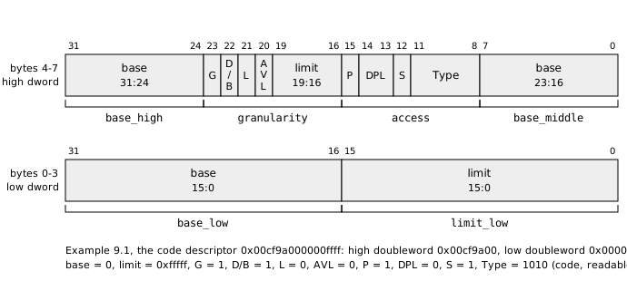
The layout looks scrambled because it is historical: the 80286 had 6-byte descriptors with a 24-bit base and a 16-bit limit, and the 80386 extended them to 32 bits by adding the two upper bytes, putting the extra 8 bits of base and 4 bits of limit wherever there was room. Read the layout as three logical values and a handful of flags:
The base is the 32-bit linear address where the segment starts, split in three pieces (bits 15:0, 23:16, 31:24).
The limit is a 20-bit value, split in two pieces, that gives the size of the segment minus one. Its unit depends on the G (granularity) flag: with
G = 0the limit is in bytes, so a segment can be at most 1 MiB; withG = 1the limit is in 4 KiB pages, so a limit of0xFFFFFmeans0x100000pages of 4 KiB, that is, all 4 GiB of the 32-bit address space. Section 3.4.5 states exactly how the processor computes the last valid offset in both cases.D/B selects the default operand and address size of the segment:
1means the code in this segment is 32-bit code,0means 16-bit code. This is the bit that turnsmov ax, 0x10into a 16-bit or a 32-bit instruction; we will see its effect in the debugger.L is for 64-bit code segments and must be 0 for us. AVL is a bit the processor ignores, left for the operating system.
P says that the segment is present in memory. Loading a selector whose descriptor has
P = 0raises a segment-not-present fault (#NP); operating systems once used that to implement swapping at the segment level.DPL is the privilege level of the segment, 0 (most privileged) to 3 (least).
S tells whether the descriptor describes a code or data segment (
S = 1) or a system segment (S = 0), and Type then says which kind. Both are explained below.
Everything in this chapter uses two descriptors: a code segment and a
data segment, both with base 0 and limit 0xFFFFF with
G = 1, that is, both covering the whole 4 GiB. Here they
are, as the bootloader writes them in assembly, one 16-bit word at a
time, low word first:
    dw 0xffff, 0x0000, 0x9a00, 0x00cf           ; 0x08: code, base 0, limit 4 GiB
    dw 0xffff, 0x0000, 0x9200, 0x00cf           ; 0x10: data, base 0, limit 4 GiB
Example 9.1. Let us decode the code descriptor by
hand. Its 8 bytes in memory are ff ff 00 00 00 9a cf 00,
which as a little-endian 64-bit number reads
0x00cf9a000000ffff. Low doubleword 0x0000ffff:
limit bits 15:0 are 0xffff, base bits 15:0 are
0. High doubleword 0x00cf9a00: base bits 23:16
are 0x00; the next byte, 0x9a, is
1001 1010 in binary, read from bit 15 down to bit 8:
P = 1, DPL = 00, S = 1,
Type = 1010; the next byte, 0xcf, is
1100 1111: G = 1, D/B = 1,
L = 0, AVL = 0, limit bits 19:16 are
0xf; base bits 31:24 are 0x00. So: base 0,
limit 0xfffff in 4 KiB units (4 GiB), present, privilege
level 0, 32-bit code segment. The data descriptor differs in one byte
only, 0x92 instead of 0x9a:
Type = 0010.
The byte that holds P, DPL, S
and Type together is often called the access byte,
and the byte that holds G, D/B,
L, AVL and the top of the limit the
granularity byte or flags. These are not Intel’s
names, but they are the names used in most kernel source code, including
ours.
9.4.2 From figure 3-8 to a C structure
The kernel builds its descriptors in C, so figure 3-8 has to become a
struct. The natural way is to follow the byte order of the
descriptor in memory, which is what os/gdt.h does:
os/gdt.h
#ifndef GDT_H
#define GDT_H

#include <stdint.h>

/* Selectors into the kernel's GDT.  A selector is the byte offset of the
   descriptor in the table; bits 0-1 are the requested privilege level and
   bit 2 picks the LDT instead of the GDT (Intel SDM Vol. 3A, section 3.4.2
   "Segment Selectors"). */
#define GDT_KERNEL_CODE 0x08
#define GDT_KERNEL_DATA 0x10

/* One 8-byte segment descriptor, Intel SDM Vol. 3A, section 3.4.5 "Segment
   Descriptors", Figure 3-8.  The base and limit are split in pieces for
   compatibility with the 286, which had 6-byte descriptors. */
struct gdt_entry {
    uint16_t limit_low;     /* limit bits 15:0 */
    uint16_t base_low;      /* base bits 15:0 */
    uint8_t  base_middle;   /* base bits 23:16 */
    uint8_t  access;        /* P | DPL(2) | S | Type(4) */
    uint8_t  granularity;   /* G | D/B | L | AVL | limit bits 19:16 */
    uint8_t  base_high;     /* base bits 31:24 */
} __attribute__((packed));

/* Operand of LGDT, Intel SDM Vol. 3A, section 2.4.1 "Global Descriptor
   Table Register (GDTR)": 16-bit limit (size - 1) and 32-bit linear base. */
struct gdt_ptr {
    uint16_t limit;
    uint32_t base;
} __attribute__((packed));

void gdt_init(void);

#endif
The six members of struct gdt_entry are the six pieces
of the descriptor in the order they appear in memory: two 16-bit words
(low doubleword), then four bytes (high doubleword).
__attribute__((packed)) tells gcc not to
insert padding between members; without it the compiler is free to align
base_low on a 4-byte boundary, and the structure would no
longer match the 8 bytes the processor reads. Check with
sizeof(struct gdt_entry): it must be 8.
Because the base and the limit are split, filling an entry by hand is
error-prone, so gdt.c has one helper that takes a base, a
limit and the two flag bytes and scatters them into the right
members:
os/gdt.c (first part)
/* gdt.c -- the kernel's own Global Descriptor Table.
 *
 * The bootloader loaded a GDT to get into protected mode, but that table
 * lives inside the boot sector at 0x7C00, memory the kernel will reuse.  So
 * the first thing the kernel does is build its own table and load it.  For
 * now it is the same flat model: two segments covering all 4 GiB, so that a
 * linear address equals a physical address and C pointers "just work".
 */
#include "gdt.h"

/* Access byte bits, Intel SDM Vol. 3A, section 3.4.5.1 "Code- and
   Data-Segment Descriptor Types", Table 3-1. */
#define ACC_PRESENT   0x80  /* P: segment is in memory */
#define ACC_RING0     0x00  /* DPL = 0 */
#define ACC_CODE_DATA 0x10  /* S: code or data (not a system segment) */
#define ACC_EXEC      0x08  /* Type bit 3: executable */
#define ACC_RW        0x02  /* Type bit 1: readable (code) / writable (data) */

/* Granularity byte high nibble. */
#define GRAN_4K       0x80  /* G: limit is counted in 4 KiB pages */
#define GRAN_32BIT    0x40  /* D/B: 32-bit operands and addresses */

static struct gdt_entry gdt[3];
static struct gdt_ptr   gdt_pointer;

/* Fill entry `index` so that it describes [base, base + limit]. */
static void gdt_set_entry(int index, uint32_t base, uint32_t limit,
                          uint8_t access, uint8_t flags)
{
    struct gdt_entry *e = &gdt[index];

    e->base_low    = base & 0xFFFF;
    e->base_middle = (base >> 16) & 0xFF;
    e->base_high   = (base >> 24) & 0xFF;

    e->limit_low   = limit & 0xFFFF;
    e->granularity = (limit >> 16) & 0x0F;   /* limit bits 19:16 */
    e->granularity |= flags & 0xF0;          /* G, D/B, L, AVL */

    e->access = access;
}
Compare the shifts and masks with the two tables above:
base >> 16 is bits 23:16,
base >> 24 is bits 31:24,
limit >> 16 masked with 0x0F is limit
bits 19:16, which share a byte with the four flags in the high nibble.
The ACC_ and GRAN_ constants are the bits of
figure 3-8 given names: 0x80 is bit 7 of the access byte,
which is bit 15 of the high doubleword, P;
0x10 is bit 4, which is S; and so on.
ACC_PRESENT | ACC_RING0 | ACC_CODE_DATA | ACC_EXEC | ACC_RW
is 0x9a, the access byte of example 9.1.
9.4.3 Types of descriptors
With S = 1, the four Type bits are
described in the Intel SDM Volume 3A, section 3.4.5.1 “Code- and
Data-Segment Descriptor Types”, table 3-1. Bit 11 (the top bit of the
field) tells code from data:
For a data segment (bit 11 = 0) the other bits are E (expand-down, for stacks that grow toward lower addresses and need their limit interpreted the other way round), W (writable; a data segment is always readable) and A (accessed).
For a code segment (bit 11 = 1) they are C (conforming, a privilege-related property we meet in chapter 13), R (readable; code segments are never writable, and a non-readable code segment cannot even be read as data) and A (accessed).
Our code descriptor has Type = 1010: code,
non-conforming, readable, not accessed. Our data descriptor has
Type = 0010: data, expand-up, writable, not accessed. The
A bit is special: the processor sets it
whenever it loads the descriptor into a segment register. It is the one
field of a descriptor that the hardware writes, and we will catch it in
the act with the debugger later in this chapter.
With S = 0, the descriptor is a system
descriptor, and the Type field means something else
entirely. Section 3.5 “System Descriptor Types”, table 3-2, lists them:
LDT descriptors, task-state segment (TSS) descriptors,
and three kinds of gates: call gates, interrupt gates, trap
gates (and task gates, which no modern system uses). A gate is a
descriptor that does not describe memory at all, but a controlled entry
point into code of a higher privilege level. We name them here so that
you recognize them in the manual; interrupt and trap gates are the
subject of chapter 11, Interrupts, and the TSS appears in chapter 13,
Processes. For this chapter, S is always 1.
9.5 Descriptor tables and selectors
9.5.1 The GDT and the GDTR
Descriptors live in memory, in a table, and the processor needs to know where that table is. The Intel SDM Volume 3A, section 3.5.1 “Segment Descriptor Tables”, figure 3-10, shows the two kinds of tables: the Global Descriptor Table (GDT), of which there is exactly one in the system, and Local Descriptor Tables (LDT), of which there may be one per task. The LDT was meant to give each program its own private set of segments; no mainstream operating system uses it any more, and neither do we. Everything in this book goes in the GDT.
The GDT is simply an array of 8-byte descriptors. Its location and
size are held in a dedicated register, the GDTR, described in section
2.4.1 “Global Descriptor Table Register (GDTR)”: a 32-bit linear
base address and a 16-bit limit, which is the size of
the table in bytes minus one. The lgdt instruction loads
the GDTR from a 6-byte structure in memory, called a
pseudo-descriptor (figure 3-11), whose layout is the limit
followed by the base; struct gdt_ptr in gdt.h
is exactly that. A GDT with three entries occupies 24 bytes, so its
limit is 23, 0x17; keep that number in mind, we will read
it out of the processor.
The first entry of the GDT is never used. The processor
treats a selector of 0 as the null selector (section 3.4.2):
loading it into DS, ES, FS or
GS is allowed and is a way to say “this register points
nowhere”, but any memory access through a null selector raises a
general-protection fault (#GP), and loading it into
CS or SS faults immediately. Entry 0 therefore
holds eight zero bytes, the null descriptor. This is why both
GDTs in this chapter have three entries for two segments.
9.5.2 Segment selectors
A segment register holds a 16-bit segment selector, section 3.4.2 “Segment Selectors”, figure 3-6:
| Bits | Field |
|---|---|
| 0–1 | RPL: requested privilege level |
| 2 | TI: table indicator (0 = GDT, 1 = LDT) |
| 3–15 | index into the descriptor table |
Since the index starts at bit 3 and a descriptor is 8 bytes, a
selector with TI = 0 and RPL = 0 is
numerically the byte offset of the descriptor in the GDT. That
is why selector 0x08 denotes the second entry (index 1, our
code segment) and 0x10 the third (index 2, our data
segment), and why GDT_KERNEL_CODE and
GDT_KERNEL_DATA in gdt.h are offsets. The
processor multiplies the index by 8, adds the GDTR base, checks that the
result does not exceed the GDTR limit (otherwise #GP), and
reads the descriptor.
Example 9.2. What selector denotes the fourth entry
of the GDT, for use at privilege level 3? Index 3 goes in bits 3–15:
3 << 3 = 0x18. TI = 0, and
RPL = 3 goes in bits 0–1: 0x18 | 3 = 0x1b.
Chapter 13 uses exactly such selectors for user-mode code.
Section 3.4.3 “Segment Registers” explains something essential for
the rest of the chapter: a segment register has a visible part,
the selector, and a hidden part (figure 3-7), in which the
processor caches the base, limit and access information of the
descriptor at the time the selector is loaded. All later
address computations use the hidden part; the GDT in memory is not
consulted again. Two consequences follow. First, changing the GDT, or
loading a new GDTR with lgdt, changes nothing visible until
each segment register is reloaded. Second, the code segment register
CS cannot be loaded with mov; the only ways to
reload it are a far jump, a far call, a far return and an interrupt
return. Both consequences shape the code of this chapter.
9.5.3 The flat model
Which segments should a kernel define? Section 3.2 “Using Segments”
presents the choices, and section 3.2.1 “Basic Flat Model” describes the
one that every modern 32-bit kernel uses: one code segment and one data
segment, both with base 0 and a 4 GiB limit, overlapping entirely. With
such segments a logical address selector:offset maps to
linear address offset, segments become invisible to C code,
and a pointer is just a linear address. Protection is then done with
paging (chapter 12), which is finer-grained and which 64-bit mode makes
mandatory anyway: in 64-bit mode the base and limit of CS,
DS, ES and SS are ignored, which
is Intel’s way of saying that the flat model won.
Why keep segmentation at all, then? Because it cannot be turned off:
protected mode requires a valid CS, and CS
requires a code descriptor in a GDT. The flat model is the minimal use
of segmentation, not its absence. The GDT still grows a little in later
chapters: user-mode code and data segments with DPL = 3 and
a TSS descriptor for chapter 13, which is the reason the kernel keeps
its GDT in C rather than in the bootloader.
9.5.4 Privilege levels
The DPL of a descriptor, the RPL of a
selector and the current privilege level CPL (the
low two bits of CS) are the three numbers behind the
“rings” of x86: ring 0 for the kernel, ring 3 for applications. The
processor compares them on every segment load and on every control
transfer, and refuses accesses from a less privileged ring to a more
privileged segment. The rules are in the Intel SDM Volume 3A, chapter 6
“Protection”, section 6.5 “Privilege Levels”. Everything in this chapter
runs at CPL = 0 with DPL = 0 descriptors, so
no check can fail; we come back to the chapter 6 rules when the first
user program runs, in chapter 13.
9.6 Switching to protected mode
The Intel SDM Volume 3A, section 12.9 “Mode Switching”, and in
particular 12.9.1 “Switching to Protected Mode”, gives the recipe as a
numbered list. In short: disable interrupts; execute lgdt;
set the PE bit of CR0; immediately
execute a far jmp or call; load the LDT and
the task register if they are used; reload the data segment registers,
which still contain real-mode values; execute lidt; enable
interrupts. We need the first four steps and the data-segment reload
now. The LDT and task register wait for chapter 13 and the IDT for
chapter 11; interrupts stay disabled until then.
CR0 is the first of the control registers,
section 2.5 “Control Registers”, figure 2-7. Its bit 0 is
PE, Protection Enable: the processor is in protected mode
when and only when this bit is 1. Bit 31, PG, enables
paging and is the subject of chapter 12. CR0 can only be
read and written with mov to and from a general
register.
The rest of this section walks through
bootloader/bootloader.asm, the chapter 7 bootloader
rewritten for this recipe. It also changes how the kernel is read from
disk, so that it works on a hard disk image, which is what this chapter
boots from. The file is shown in pieces, in order.
9.6.1 Segments and the stack
bootloader/bootloader.asm (part 1)
;******************************************************************************
; bootloader.asm -- chapter 9
;
; The BIOS loads this sector at 0000:7C00 and jumps to it with the CPU in
; real mode and DL holding the number of the boot drive.  The bootloader
;   1. sets up segment registers and a stack,
;   2. reads the kernel ELF file from disk sector 1 onwards into physical
;      memory at 0x10000 with the BIOS extended read service (LBA),
;   3. enables the A20 address line,
;   4. loads a temporary GDT, switches to 32-bit protected mode,
;   5. jumps to the kernel entry point stored in the ELF header.
;
; Everything here must fit in 512 bytes, including the boot signature.
;******************************************************************************
bits 16

%ifndef KERNEL_SECTORS
%error "KERNEL_SECTORS must be defined on the nasm command line"
%endif

KERNEL_SEG      equ 0x1000      ; 1000:0000 = physical 0x10000 (code/README.md)
KERNEL_PHYS     equ 0x10000
ELF_ENTRY_OFF   equ 0x18        ; e_entry in the ELF32 header (ELF spec, "ELF Header")
STACK_TOP_32    equ 0x90000     ; initial kernel stack (code/README.md)
SECTORS_PER_CALL equ 64         ; many BIOSes refuse more than 127, some 64
                                ; (OSDev wiki: "ATA in x86 RealMode (BIOS)")

;------------------------------------------------------------------------------
; 1. Segments and stack.
;    The BIOS does not guarantee any segment register value except that
;    CS:IP points to 7C00h, so set them all to zero and use offsets equal
;    to physical addresses.  The stack grows down from 7C00h, below us.
;------------------------------------------------------------------------------
start:
    cli
    cld
    xor     ax, ax
    mov     ds, ax
    mov     es, ax
    mov     ss, ax
    mov     sp, 0x7c00
    mov     [boot_drive], dl    ; BIOS passes the boot drive in DL
There is no org 0x7c00 any more: as in chapter 8, the
bootloader is assembled to an ELF object and linked at
0x7c00 by bootloader.lds, so that
gdb can show its source. KERNEL_SECTORS is not
defined in the file; the %ifndef block makes
nasm stop with an error unless the Makefile defines it on
the command line, which it does as explained below. The constants come
from the memory map in code/README.md: the kernel ELF file
goes to physical address 0x10000, which real mode addresses
as 1000:0000, and the kernel stack starts at
0x90000 and grows down.
The BIOS jumps to 0000:7C00 on some machines and to
07C0:0000 on others, the same physical address with
different segment values, and it leaves the other segment registers as
they were. The first lines therefore set DS,
ES and SS to zero, so that every address in
the file is a physical address, and put the stack just below the
bootloader. cli disables interrupts: step 1 of the Intel
recipe, done first because changing SS and SP
with interrupts enabled is unsafe. cld clears the direction
flag so that string instructions go upward. DL holds the
number of the drive the BIOS booted from (0x00 for the
first floppy, 0x80 for the first hard disk); we save it
because the disk read below needs it and DL is about to be
reused.
9.6.2 Reading the kernel by LBA
Chapter 7 read the floppy with INT 13h, AH=02h, which
takes a cylinder, head and sector number. That is the natural way to
address a floppy, whose geometry is physical and fixed. It is the wrong
way to address a hard disk: a modern disk has no meaningful cylinders
and heads (it may not even have platters), the geometry the BIOS reports
is a translation invented for compatibility, and the CHS fields of
AH=02h cannot address more than about 8 GiB. Hard disks are
addressed by Logical Block Address (LBA): sectors are numbered
0, 1, 2, … from the start of the disk, and that is all. The BIOS offers
an LBA read as INT 13h, AH=42h, “Extended Read”, documented
in Ralf Brown’s Interrupt List; the OSDev wiki page “Disk access using
the BIOS (INT 13h)” summarizes it. Instead of registers, the parameters
are passed in a small structure in memory, the Disk Address
Packet (DAP), whose address is in DS:SI:
| Offset | Size | Field |
|---|---|---|
| 0 | 1 | size of the packet, 0x10 |
| 1 | 1 | reserved, 0 |
| 2 | 2 | number of sectors to transfer |
| 4 | 4 | destination buffer, as offset (low word) then segment (high word) |
| 8 | 8 | first sector, as a 64-bit LBA |
On return the carry flag is clear on success and set on error, with
an error code in AH. The BIOS may also overwrite the
count field of the DAP with the number of sectors actually
transferred, which is why the code below keeps its own counters in
registers rather than trusting the packet.
bootloader/bootloader.asm (part 2)
;------------------------------------------------------------------------------
; 2. Read the kernel.
;    INT 13h, AH=42h "Extended Read" takes a Disk Address Packet (DAP) in
;    DS:SI and addresses the disk by LBA, so no CHS geometry is needed
;    (Ralf Brown's Interrupt List, INT 13h AH=42h; OSDev wiki: "Disk access
;    using the BIOS (INT 13h)").  Each call transfers at most SECTORS_PER_CALL
;    sectors; the destination advances by 32 paragraphs per sector
;    (512 bytes / 16 bytes per paragraph) so a segment can address it.
;------------------------------------------------------------------------------
    mov     cx, KERNEL_SECTORS  ; sectors still to read
.read_chunk:
    test    cx, cx
    jz      .read_done
    mov     ax, cx
    cmp     ax, SECTORS_PER_CALL
    jbe     .count_ok
    mov     ax, SECTORS_PER_CALL
.count_ok:
    mov     [dap.count], ax
    sub     cx, ax
    push    ax                  ; sectors in this chunk
    push    cx                  ; sectors remaining
    mov     si, dap
    mov     dl, [boot_drive]
    mov     ah, 0x42
    int     0x13
    jc      disk_error          ; CF=1 means the BIOS reported an error
    pop     cx
    pop     ax
    add     [dap.lba], ax       ; next LBA (32-bit add done in two halves)
    adc     word [dap.lba + 2], 0
    shl     ax, 5               ; sectors -> paragraphs (x32)
    add     [dap.segment], ax   ; next destination segment
    jmp     .read_chunk
.read_done:
Why a loop, when one call could ask for all
KERNEL_SECTORS sectors? Two limits. First, BIOSes cap the
number of sectors per call: the EDD specification allows 127, and some
implementations refuse more than 64, so we never ask for more than
SECTORS_PER_CALL = 64. Second, the destination is a
real-mode segment:offset pair, and the offset is 16-bit: a
buffer of more than 64 KiB cannot be described with a fixed segment,
because the offset wraps around. The loop therefore keeps the offset at
0 and advances the segment after each chunk: one sector is 512
bytes, a segment unit (a paragraph) is 16 bytes, so each sector
read moves the segment by 32, hence shl ax, 5. The LBA is
advanced in the same step. Since the LBA field is 64 bits and we only
have 16-bit registers, the addition is done on the low word with
add and the carry propagated into the next word with
adc; the upper 32 bits can never be reached by a kernel of
less than 1 MiB and are left alone.
CX counts the sectors still to read, AX the
sectors of the current chunk; both are pushed around the
int 0x13 call because the BIOS is free to clobber them.
With a 42-sector kernel the loop runs once; exercise 9.4 makes it run
several times.
9.6.3 Enabling the A20 line
bootloader/bootloader.asm (part 3)
;------------------------------------------------------------------------------
; 3. Enable A20.
;    The 8086 had 20 address lines, so FFFF:FFFF wrapped around to 0FFEFh.
;    For compatibility, PCs gate address line 20 off at power-up; with it
;    off, every odd megabyte is an alias of the even one below it.  Bit 1 of
;    the System Control Port A (I/O port 92h) turns the line on; bit 0 of the
;    same port resets the CPU, so it must stay clear (OSDev wiki: "A20 Line",
;    "Fast A20 Gate").  QEMU and every chipset since the late 1990s support
;    this; the older keyboard-controller method is longer and not needed.
;------------------------------------------------------------------------------
    in      al, 0x92
    or      al, 0x02
    and     al, 0xfe
    out     0x92, al
This is a piece of PC archaeology that every bootloader must carry.
The 8086 had 20 address lines, so its highest address was
0xFFFFF; the highest segment:offset pair,
FFFF:FFFF, computes to 0x10FFEF, one bit too
many, and on the 8086 that bit simply did not exist: the address wrapped
around to 0x0FFEF. Some programs relied on the wrap-around.
When the 80286 arrived with 24 address lines, IBM made the PC/AT behave
like an 8086 at power-up by gating the twenty-first address
line, A20, to zero through a spare pin of the keyboard controller, and
the gate has been there ever since. The Intel SDM Volume 3A, section
12.1.1 “Processor State After Reset”, describes the state of the
processor after reset; the A20 gate is not part of it, because it sits
outside the processor, in the chipset. The OSDev wiki page “A20 Line”
tells the whole story and lists the ways to open the gate.
While the gate is closed, bit 20 of every address is forced to zero,
so the memory at 0x100000 is an alias of the memory at
0x000000, and a kernel that writes above 1 MiB corrupts the
first megabyte instead. Nothing in this chapter uses memory above 1 MiB,
but chapter 12 does, and a bootloader that leaves the gate closed
produces bugs that are very hard to find later, so we open it now. The
fastest way, supported by QEMU and by every chipset of the last
twenty-five years, is bit 1 of System Control Port A, I/O port
0x92. The code reads the port, sets bit 1 and writes it
back. The and al, 0xfe is not decoration: bit 0 of the
same port is “fast reset”, and writing a 1 to it reboots the
machine. Read-modify-write with bit 0 forced to zero is the only
safe sequence.
9.6.4 Loading the GDT and setting CR0.PE
bootloader/bootloader.asm (part 4)
;------------------------------------------------------------------------------
; 4. Enter protected mode.
;    Intel SDM Vol. 3A, section 12.9.1 "Switching to Protected Mode":
;    disable interrupts, LGDT, set CR0.PE, then a far JMP to load CS and
;    flush the prefetched real-mode instructions.  After the jump the
;    data-segment registers still hold real-mode values, so they are
;    reloaded with the flat data selector.
;------------------------------------------------------------------------------
    lgdt    [gdt_descriptor]
    mov     eax, cr0
    or      eax, 1              ; CR0.PE (Intel SDM Vol. 3A, section 2.5)
    mov     cr0, eax
    jmp     GDT_CODE:protected_mode

bits 32
protected_mode:
    mov     ax, GDT_DATA
    mov     ds, ax
    mov     es, ax
    mov     fs, ax
    mov     gs, ax
    mov     ss, ax
    mov     esp, STACK_TOP_32
Here are steps 2, 3 and 4 of section 12.9.1 in five instructions.
lgdt [gdt_descriptor] loads the GDTR from the
pseudo-descriptor defined at the end of the file. The three
cr0 instructions set PE. From the instant
mov cr0, eax retires, the processor is in protected mode,
but nothing has changed yet: CS still holds the real-mode
value 0, and its hidden part still describes a 16-bit segment with base
0, so the next instruction is fetched and executed as before. The manual
insists that the far jump come immediately after
mov cr0: the processor has already decoded a few
instructions past the current one (the prefetch queue), decoded
as 16-bit code, and a far jump, which is a serializing instruction,
discards them and starts over. Code placed between mov cr0
and the jump works on some processors and fails randomly on others.
jmp GDT_CODE:protected_mode is a far jump: it loads
CS with the selector 0x08 and EIP
with the offset of protected_mode. Loading CS
makes the processor fetch descriptor 1 from the new GDT into the hidden
part of CS, and that descriptor has D/B = 1,
so from the destination onward, instructions are decoded as 32-bit. That
is why the source file says bits 32 right there:
nasm must encode mov ax, GDT_DATA and the
following instructions the way a 32-bit processor will decode them.
Then, step 9: DS, ES, FS,
GS and SS still hold 0, a null selector, and
any data access through them would fault, so they are reloaded with the
data selector 0x10, and the stack pointer is set to the
kernel stack top.
9.6.5 Jumping to the kernel and the error path
bootloader/bootloader.asm (part 5)
;------------------------------------------------------------------------------
; 5. Jump to the kernel.  The ELF header is at KERNEL_PHYS, and e_entry
;    (offset 0x18) holds the virtual address of _start.  The kernel is
;    linked so that virtual == physical, so we can jump there directly.
;------------------------------------------------------------------------------
    mov     eax, [KERNEL_PHYS + ELF_ENTRY_OFF]
    jmp     eax

;------------------------------------------------------------------------------
; Error path (still 16-bit): print one character with the BIOS teletype
; service (INT 10h, AH=0Eh) and halt.
;------------------------------------------------------------------------------
bits 16
disk_error:
    mov     ah, 0x0e
    mov     al, 'E'
    mov     bx, 0x0007          ; page 0, light grey on black
    int     0x10
.halt:
    cli
    hlt
    jmp     .halt
The jump to the kernel is the one from chapter 8: the ELF header sits
at the start of the loaded file, e_entry is at offset
0x18 in it (chapter 5, The Anatomy of a Program), and the
kernel is linked so that the address in e_entry is also the
physical address where the code was loaded. The two differences from
chapter 8 are the base address, 0x10000 instead of
0x500, and the fact that the jump is now a 32-bit
jmp eax, executed in protected mode.
disk_error is reached from the read loop if the BIOS
sets the carry flag. It is 16-bit code, because the mode switch has not
happened yet at that point, hence the bits 16 directive
before it; it prints a single E with the BIOS teletype
service (INT 10h, AH=0Eh, the service the chapter 7
exercise used) and halts. A single letter is all the 512-byte budget
allows, and it is enough: if the machine shows E, the disk
image is wrong, not the kernel.
9.6.6 Data: the DAP, the GDT and its pseudo-descriptor
bootloader/bootloader.asm (part 6)
;------------------------------------------------------------------------------
; Data
;------------------------------------------------------------------------------
boot_drive: db 0

; Disk Address Packet for INT 13h AH=42h (Ralf Brown's Interrupt List).
align 4
dap:
    db 0x10                     ; size of this packet
    db 0                        ; reserved
.count:   dw 0                  ; number of sectors to transfer
.offset:  dw 0                  ; destination offset
.segment: dw KERNEL_SEG         ; destination segment
.lba:     dq 1                  ; first sector: the kernel starts at LBA 1

; Temporary GDT: a null descriptor and two flat 4 GiB segments.
; Descriptor layout, Intel SDM Vol. 3A, section 3.4.5 "Segment Descriptors":
;   limit[15:0] | base[15:0] | base[23:16] | access | flags:limit[19:16] | base[31:24]
; access 0x9A = present, DPL 0, code, execute/read;  0x92 = data, read/write
; flags  0xC  = granularity 4 KiB (G=1), 32-bit operands (D/B=1)
align 8
gdt:
    dq 0                                        ; 0x00: null descriptor
    dw 0xffff, 0x0000, 0x9a00, 0x00cf           ; 0x08: code, base 0, limit 4 GiB
    dw 0xffff, 0x0000, 0x9200, 0x00cf           ; 0x10: data, base 0, limit 4 GiB
gdt_end:
GDT_CODE equ 0x08
GDT_DATA equ 0x10

; Pseudo-descriptor for LGDT (Intel SDM Vol. 3A, section 2.4.1): limit, base.
gdt_descriptor:
    dw gdt_end - gdt - 1
    dd gdt

; Pad to 510 bytes and append the boot signature the BIOS looks for.
times 510 - ($ - $$) db 0
dw 0xaa55
The DAP is the structure of the table above, with the destination
1000:0000 and the starting LBA 1, since sector 0 is the
bootloader itself (see “Disk image layout” in
code/README.md). The GDT is the one decoded in example 9.1,
written as words so that each descriptor fits on one line;
align 8 is a courtesy to the processor, which fetches
descriptors faster when they are aligned. The pseudo-descriptor’s limit
is computed by the assembler as gdt_end - gdt - 1 = 23.
Note that the GDT lives inside the boot sector, in the memory
at 0x7C00 that the kernel is free to reuse; that is the
reason the kernel builds its own GDT, below.
9.6.7 The 512-byte budget
The bootloader must still fit in one sector, signature included.
nasm -l produces a listing with the address of each line,
and shows how much room is left:
$ nasm -f elf -F dwarf -g -DKERNEL_SECTORS=42 bootloader/bootloader.asm -o /tmp/b.o -l /tmp/b.lst
$ grep "times 510\|0xaa55" /tmp/b.lst
   177 000000BE 00<rep 140h>            times 510 - ($ - $$) db 0
   178 000001FE 55AA                    dw 0xaa55
Code and data end at offset 0xBE: 190 bytes used,
0x140 = 320 bytes of padding, 2 bytes of signature. The
disk read, the A20 gate, the mode switch and a GDT fit in 190 bytes;
there is room for the exercises. The bootloader/Makefile
refuses to build an image if the output is not exactly 512 bytes.
9.6.8 Building the bootloader
bootloader/bootloader.lds
/* Link the bootloader at 0x7C00, the address where the BIOS loads the first
   sector of the boot drive (chapter 7).  Only .text is kept: the assembly
   file puts code, data and the boot signature in that single section so
   that `times 510 - ($ - $$)` can pad the whole thing to 512 bytes. */
OUTPUT(bootloader);

PHDRS
{
  text PT_LOAD FILEHDR PHDRS;
}

SECTIONS
{
  . = SIZEOF_HEADERS;
  .text 0x7c00 : { *(.text) } :text
  /DISCARD/ : { *(.note.*) *(.comment) }
}
bootloader/Makefile
BUILD_DIR=../build/bootloader
BOOTLOADER=$(BUILD_DIR)/bootloader.bin

# KERNEL_SECTORS is passed on the command line by the top-level Makefile.
# The default lets `make -C bootloader` work on its own for experiments.
KERNEL_SECTORS ?= 64

all: $(BOOTLOADER)

# nasm -f elf + ld keep the DWARF line information so that gdb can show
# the bootloader source; objcopy -O binary then strips everything down to
# the 512 bytes the BIOS loads.  The bootloader depends on the kernel file
# so that it is re-assembled when the kernel changes size.
$(BUILD_DIR)/bootloader.o: bootloader.asm ../build/os/os
    mkdir -p $(BUILD_DIR)
    nasm -f elf -F dwarf -g -DKERNEL_SECTORS=$(KERNEL_SECTORS) $< -o $@

$(BUILD_DIR)/bootloader.elf: $(BUILD_DIR)/bootloader.o bootloader.lds
    ld -m elf_i386 --no-warn-rwx-segments -T bootloader.lds $< -o $@

$(BOOTLOADER): $(BUILD_DIR)/bootloader.elf
    objcopy -O binary $< $@
    @test $$(stat -c %s $@) -eq 512 || { echo "bootloader is not 512 bytes"; exit 1; }

clean:
    rm -rf $(BUILD_DIR)
The three-step build is the one introduced in chapter 8:
nasm -f elf -g keeps the labels and line numbers,
ld places .text at 0x7c00,
objcopy -O binary extracts the raw 512 bytes. Two things
are new. -DKERNEL_SECTORS=... defines the assembler symbol
that the source demands, and the object file depends on the kernel
executable ../build/os/os: when the kernel grows by a
sector, make reassembles the bootloader with the new count.
Where the count comes from is in the top-level Makefile:
Makefile
# Chapter 9: protected mode and descriptors.
#
# From this chapter on the disk image is a 4 MiB hard-disk image (see
# code/README.md, "Disk image layout"): sector 0 holds the bootloader and
# the kernel ELF starts at sector 1.  QEMU attaches it as an IDE/SATA drive
# and SeaBIOS boots it like a real PC would.
BUILD_DIR=build
BOOTLOADER=$(BUILD_DIR)/bootloader/bootloader.bin
OS=$(BUILD_DIR)/os/os
DISK_IMG=$(BUILD_DIR)/disk.img

all: bootdisk

.PHONY: all bootloader os bootdisk qemu gdb clean test

os:
    $(MAKE) -C os

# The bootloader needs to know how many 512-byte sectors the kernel file
# occupies (rounded up), so it is assembled after the kernel is linked.
bootloader: os
    $(MAKE) -C bootloader KERNEL_SECTORS=$$(( ($$(stat -c %s $(OS)) + 511) / 512 ))

# 8192 sectors x 512 bytes = 4 MiB.  conv=notrunc keeps the image size.
bootdisk: bootloader os
    dd if=/dev/zero of=$(DISK_IMG) bs=512 count=8192 status=none
    dd conv=notrunc if=$(BOOTLOADER) of=$(DISK_IMG) bs=512 count=1 seek=0 status=none
    dd conv=notrunc if=$(OS) of=$(DISK_IMG) bs=512 seek=1 status=none

# -S stops the CPU before the first instruction; -gdb opens a gdb stub.
qemu: bootdisk
    qemu-system-i386 -machine q35 -drive format=raw,file=$(DISK_IMG),if=ide -gdb tcp::26000 -S

# -nx: ignore ~/.gdbinit and gdb's auto-load safe-path rules; -x: run ours.
gdb:
    gdb -q -nx -x .gdbinit

clean:
    $(MAKE) -C bootloader clean
    $(MAKE) -C os clean
    rm -rf $(BUILD_DIR)

# Boot headless, stop at kmain and verify that CR0.PE is set.
test: bootdisk
    ../../../tools/pmode-test.sh $(DISK_IMG) $(OS) kmain
The bootloader target builds the kernel first, then asks
the shell for the kernel file size with stat -c %s and
rounds it up to whole sectors with integer arithmetic ($$
is how a Makefile writes a single $ for the shell). The
disk image is no longer a 1.44 MB floppy but a 4 MiB hard-disk image,
and the qemu target attaches it with
-drive format=raw,file=...,if=ide. On the q35
machine, SeaBIOS finds the drive behind an AHCI (SATA) controller and
boots from it. The bootloader does not know and does not care:
INT 13h hides floppy, IDE and AHCI behind the same
interface, and that is precisely what BIOS services are for. The price
is paid later: once in protected mode the BIOS is gone, and chapter 14
has to drive the disk controller itself.
9.7 The kernel side
The kernel of this chapter is four small files: a linker script, an
assembly entry point, the GDT code and kernel.c. It is the
chapter 8 program, rearranged so that it keeps working once we add to
it.
9.7.1 The linker script
os/os.lds
/* Linker script for the kernel (chapters 9 and up).

   The bootloader copies the whole ELF file verbatim to physical 0x10000 and
   jumps to e_entry, so the file layout IS the memory layout:

     file offset 0x000  ->  0x10000  ELF header + program headers
     file offset 0x100  ->  0x10100  .text, then .rodata, .data, .bss

   ALIGN(0x100) on .text also aligns its FILE offset to 0x100 (with -nmagic
   ld packs sections and aligns the offset like the address), which is what
   makes the headers land exactly 0x100 bytes before the code. */
ENTRY(_start);

PHDRS
{
  /* The program header table itself must live inside a loadable segment,
     otherwise recent versions of ld refuse to link ("PHDR segment not
     covered by LOAD segment").  FILEHDR and PHDRS on the code segment tell
     ld to place the ELF header and the program headers at its start. */
  headers PT_PHDR PHDRS;
  code PT_LOAD FILEHDR PHDRS;
}

SECTIONS
{
  .text 0x10100 : ALIGN(0x100) { *(.text .text.*) } :code
  .rodata : { *(.rodata .rodata.*) } :code
  .data   : { *(.data .data.*) } :code
  /* __bss_start/__bss_end let entry.asm zero .bss: the bootloader copies
     the FILE, and .bss has no bytes in the file (NOBITS), so the memory it
     occupies holds whatever followed .data in the file (debug sections)
     until the kernel clears it.  A real ELF loader zeroes MemSiz - FileSiz
     for us; ours does not. */
  .bss    : { __bss_start = .; *(.bss .bss.*) *(COMMON) __bss_end = .; } :code
  /DISCARD/ : { *(.eh_frame) *(.note.*) *(.comment) }
}
Compared with the chapter 8 script, four things changed:
The entry point is
_start, an assembly label, rather thanmain. A C function expects a stack and zeroed globals;_startprovides them before calling C.The load address is
0x10000..textis placed at0x10100, withALIGN(0x100), and this is the detail that makes the whole scheme work: with-nmagic,ldlays out the file without page alignment and gives each section a file offset congruent to its address modulo its alignment, so.textlands at file offset0x100, and theLOADsegment, which starts with the ELF header (FILEHDR) and the program headers (PHDRS), starts at file offset 0 and address0x10000. The bootloader copies the file as it is to0x10000, so the header is at0x10000,e_entryat0x10018, and.textat0x10100. Chapter 8 relied on the same alignment rule without saying so; now it is stated..rodataand.datasections are collected too, since the kernel now has a string literal. All of them go into the singlecodesegment: a kernel this small gains nothing from separate read-only and writable segments, and protection by segment is not the way we go anyway.Two symbols,
__bss_startand__bss_end, are defined around the.bssoutput section, for the entry code to use. Why they are needed is explained withentry.asm.
9.7.2 The entry point and what a loader really does
os/entry.asm
;******************************************************************************
; entry.asm -- the kernel's first instructions.
;
; The bootloader jumps here in 32-bit protected mode with a flat GDT loaded.
; The kernel sets its own stack so that it does not depend on whatever the
; bootloader chose, clears .bss, then calls the C function kmain.  kmain must never
; return; if it does, halt forever.
;******************************************************************************
bits 32

KERNEL_STACK_TOP equ 0x90000    ; code/README.md, "Memory map"

section .text
global _start
extern kmain
extern __bss_start, __bss_end    ; defined in os.lds

_start:
    mov     esp, KERNEL_STACK_TOP

    ; Zero .bss.  C guarantees that uninitialised globals start at zero,
    ; and the compiler relies on it; nobody else does it for us here.
    cld
    xor     eax, eax
    mov     edi, __bss_start
    mov     ecx, __bss_end
    sub     ecx, edi
    rep     stosb               ; ECX bytes of AL at ES:EDI

    call    kmain
.halt:
    cli                         ; no interrupts can wake us up
    hlt                         ; stop the CPU until the next interrupt (none)
    jmp     .halt
Setting ESP again is deliberate: the bootloader did it,
but the kernel should not depend on which bootloader loaded it, and the
first thing any kernel does with a stack it did not create is to replace
it.
The .bss zeroing deserves a careful explanation, because
it is where our bootloader stops being a real loader. Recall from
chapter 5 that .bss holds the uninitialized global
variables of a program and is a NOBITS section: it has an
address and a size but no bytes in the file. The C standard
guarantees that such variables start at zero, the compiler relies on it,
and on a hosted system the operating system’s ELF loader provides the
guarantee: for each LOAD segment, it copies
FileSiz bytes from the file and then fills
MemSiz - FileSiz bytes with zero. That is what
“loading an ELF file” means; the readelf -l output below
shows our segment with FileSiz 0x29e and
MemSiz 0x2be, 32 bytes of difference, which are our
.bss.
Our bootloader does not read program headers; it copies the whole
file verbatim to 0x10000. The memory at the address of
.bss therefore receives whatever the file holds at that
file offset, and since -nmagic packs sections, that is the
beginning of the .debug_aranges section, the first
non-loadable section after .rodata. Debugging information,
in our global variables. The seven instructions between cld
and rep stosb fix that: they store
ECX = __bss_end - __bss_start bytes of zero starting at
__bss_start, the two symbols the linker script defines.
Together, the bootloader plus this stub do the job of a loader; the
debugger session later in this chapter shows the garbage before and the
zeros after.
kmain must never return. If it does, the kernel halts:
cli so that no interrupt can wake the processor (none is
enabled yet anyway), hlt to stop it, and a jump back in
case something does wake it.
9.7.3 The kernel’s own GDT
The second half of gdt.c builds the table and loads
it:
os/gdt.c (second part)
void gdt_init(void)
{
    /* Entry 0 is never used by the processor: a selector of 0 is "null"
       and loading it into DS..GS is allowed, using it faults (Intel SDM
       Vol. 3A, section 3.4.2). */
    gdt_set_entry(0, 0, 0, 0, 0);

    /* With G=1 a limit of 0xFFFFF means 0xFFFFF pages of 4 KiB = 4 GiB. */
    gdt_set_entry(1, 0, 0xFFFFF,
                  ACC_PRESENT | ACC_RING0 | ACC_CODE_DATA | ACC_EXEC | ACC_RW,
                  GRAN_4K | GRAN_32BIT);
    gdt_set_entry(2, 0, 0xFFFFF,
                  ACC_PRESENT | ACC_RING0 | ACC_CODE_DATA | ACC_RW,
                  GRAN_4K | GRAN_32BIT);

    gdt_pointer.limit = sizeof(gdt) - 1;
    gdt_pointer.base  = (uint32_t)&gdt;

    /* LGDT only changes GDTR; the segment registers still cache the old
       descriptors.  Reloading each one makes the processor fetch the new
       descriptor (Intel SDM Vol. 3A, section 3.4.3 "Segment Registers").
       CS cannot be written with MOV, so a far jump to the next instruction
       reloads it.  "1:" is a local label and "1f" means "the next 1:". */
    asm volatile(
        "lgdt %0\n\t"
        "mov %1, %%ax\n\t"
        "mov %%ax, %%ds\n\t"
        "mov %%ax, %%es\n\t"
        "mov %%ax, %%fs\n\t"
        "mov %%ax, %%gs\n\t"
        "mov %%ax, %%ss\n\t"
        "ljmp %2, $1f\n\t"
        "1:"
        : /* no outputs */
        : "m"(gdt_pointer), "i"(GDT_KERNEL_DATA), "i"(GDT_KERNEL_CODE)
        : "eax", "memory");
}
The three gdt_set_entry calls produce, byte for byte,
the three descriptors of the bootloader’s table; there is no need for
them to be different, the point is that this table is in the kernel’s
own memory (gdt is a static array in .bss),
not in the boot sector. gdt_pointer is the
pseudo-descriptor: limit sizeof(gdt) - 1 = 23, base the
address of the array.
The inline assembly is the same sequence as the bootloader’s, in
AT&T syntax, which gcc uses by default (chapter 4
describes the differences). lgdt %0 loads the GDTR from
gdt_pointer, passed as a memory operand ("m").
Then comes the part that is easy to get wrong: as section 3.4.3 says,
lgdt alone changes nothing visible, because every segment
register still holds, in its hidden part, the descriptor it loaded from
the bootloader’s table. The five mov instructions reload
DS, ES, FS, GS and
SS with 0x10, which makes the processor read
entry 2 of the new table. CS cannot be loaded with
mov, so ljmp $0x08, $1f jumps to the very next
instruction, through selector 0x08, which reloads
CS from the new table. 1: is a local
label of the GNU assembler and 1f means “the next
label named 1, forward”; such labels can be reused and are the usual way
to write a jump target inside inline assembly. The "memory"
clobber tells gcc that memory may have changed, so that it
does not keep values cached in registers across the statement.
9.7.4 kernel.c
os/kernel.c
/* kernel.c -- chapter 9: we are in protected mode. */
#include <stdint.h>
#include "gdt.h"

/* The VGA text buffer: 80x25 cells of 2 bytes each, character then
   attribute, at physical 0xB8000 (code/README.md, "Memory map"; OSDev
   wiki: "Printing to Screen").  Attribute 0x0F = white on black. */
#define VGA_MEMORY ((volatile uint16_t *)0xB8000)
#define VGA_WHITE_ON_BLACK 0x0F

static void vga_write_line(const char *s)
{
    int i;

    for (i = 0; s[i] != '\0'; i++)
        VGA_MEMORY[i] = (uint16_t)(VGA_WHITE_ON_BLACK << 8) | (uint8_t)s[i];
}

void kmain(void)
{
    gdt_init();
    vga_write_line("Protected mode OK");

    for (;;)
        asm volatile("cli; hlt");
}
The kernel can no longer print through the BIOS, so it writes to the
screen the only way left: directly into video memory. In the text mode
the BIOS leaves the display in, the VGA adapter shows 80 by 25
characters, each described by two bytes at physical address
0xB8000 onward, the character code then an attribute byte
(0x0F is white on black); writing a byte there changes the
screen immediately. That is all we need for a message; a proper driver
with a cursor, scrolling and a printf is the subject of
chapter 10, Talking to devices. The pointer is declared
volatile so that the compiler does not optimize away stores
to memory that it believes nobody reads.
kmain is now the C entry point called by
_start; its first action is gdt_init(), so
that nothing after it depends on the boot sector. Then the message, then
the same cli; hlt loop as _start, written in
C.
9.7.5 The kernel Makefile
os/Makefile
BUILD_DIR=../build/os
OS=$(BUILD_DIR)/os

# -ffreestanding -nostdlib: no C runtime, no standard library (chapter 8).
# -m32: 32-bit code.  -no-pie/-fno-pie: fixed addresses, no relocation at
# load time (see chapter 4).  -fno-asynchronous-unwind-tables and
# -fcf-protection=none keep the generated code free of .eh_frame data and
# endbr32 instructions that mean nothing on bare metal.  -fno-stack-protector:
# the stack protector needs a per-thread canary that we have not set up.
CFLAGS+=-ffreestanding -nostdlib -m32 -no-pie -fno-pie \
        -fno-asynchronous-unwind-tables -fcf-protection=none -fno-stack-protector \
        -O0 -gdwarf-4 -ggdb3 -Wall -Wextra

# entry.o is listed first so that _start is the first thing in .text.
# A .c and a .asm file must not share a base name: both would build to the
# same .o in BUILD_DIR.
ASM_SRCS := $(filter-out entry.asm, $(wildcard *.asm))
C_SRCS   := $(wildcard *.c)
OS_OBJS  := $(BUILD_DIR)/entry.o \
            $(patsubst %.asm, $(BUILD_DIR)/%.o, $(ASM_SRCS)) \
            $(patsubst %.c, $(BUILD_DIR)/%.o, $(C_SRCS))

all: $(OS)

$(BUILD_DIR)/%.o: %.asm
    mkdir -p $(BUILD_DIR)
    nasm -f elf32 -F dwarf -g $< -o $@

$(BUILD_DIR)/%.o: %.c $(wildcard *.h)
    mkdir -p $(BUILD_DIR)
    gcc $(CFLAGS) -c $< -o $@

# -nmagic: do not page-align sections, keep the file as small as its content.
$(OS): $(OS_OBJS) os.lds
    ld -m elf_i386 -nmagic --no-warn-rwx-segments -T os.lds $(OS_OBJS) -o $@

clean:
    rm -rf $(BUILD_DIR)
The compiler flags are those of chapter 0 and chapter 8, plus
-fno-stack-protector: on modern distributions
gcc enables the stack protector by default, and the code it
generates reads a canary through a segment register (%gs)
that only a hosted C runtime sets up. The object list puts
entry.o first so that _start is the first
thing in .text; the linker script could enforce it with an
input section rule, but the order of the object files is enough.
--no-warn-rwx-segments silences the warning ld
prints because our single segment is readable, writable and executable
at once, which is intentional here.
9.8 Building and debugging
All of the following runs inside the toolchain container of chapter
0, in code/chapter9/os.
9.8.1 Build
$ make
make -C os
make[1]: Entering directory '/work/code/chapter9/os/os'
mkdir -p ../build/os
nasm -f elf32 -F dwarf -g entry.asm -o ../build/os/entry.o
mkdir -p ../build/os
gcc -ffreestanding -nostdlib -m32 -no-pie -fno-pie -fno-asynchronous-unwind-tables -fcf-protection=none -fno-stack-protector -O0 -gdwarf-4 -ggdb3 -Wall -Wextra -c gdt.c -o ../build/os/gdt.o
mkdir -p ../build/os
gcc -ffreestanding -nostdlib -m32 -no-pie -fno-pie -fno-asynchronous-unwind-tables -fcf-protection=none -fno-stack-protector -O0 -gdwarf-4 -ggdb3 -Wall -Wextra -c kernel.c -o ../build/os/kernel.o
ld -m elf_i386 -nmagic --no-warn-rwx-segments -T os.lds ../build/os/entry.o   ../build/os/gdt.o  ../build/os/kernel.o -o ../build/os/os
make[1]: Leaving directory '/work/code/chapter9/os/os'
make -C bootloader KERNEL_SECTORS=$(( ($(stat -c %s build/os/os) + 511) / 512 ))
make[1]: Entering directory '/work/code/chapter9/os/bootloader'
mkdir -p ../build/bootloader
nasm -f elf -F dwarf -g -DKERNEL_SECTORS=42 bootloader.asm -o ../build/bootloader/bootloader.o
ld -m elf_i386 --no-warn-rwx-segments -T bootloader.lds ../build/bootloader/bootloader.o -o ../build/bootloader/bootloader.elf
objcopy -O binary ../build/bootloader/bootloader.elf ../build/bootloader/bootloader.bin
make[1]: Leaving directory '/work/code/chapter9/os/bootloader'
dd if=/dev/zero of=build/disk.img bs=512 count=8192 status=none
dd conv=notrunc if=build/bootloader/bootloader.bin of=build/disk.img bs=512 count=1 seek=0 status=none
dd conv=notrunc if=build/os/os of=build/disk.img bs=512 seek=1 status=none
Read the output in the order make ran it: the kernel
first, then the bootloader with KERNEL_SECTORS=42, then the
image. The sizes:
$ ls -l build/bootloader/bootloader.bin build/os/os
-rwxr-xr-x 1 1000 1000   512 Oct  9 04:36 build/bootloader/bootloader.bin
-rwxr-xr-x 1 1000 1000 21448 Oct  9 04:36 build/os/os
21448 bytes, (21448 + 511) / 512 = 42 sectors. Most of
those 21 KB are DWARF, as the next listing shows.
9.8.2 The ELF image dissected
$ readelf -l build/os/os

Elf file type is EXEC (Executable file)
Entry point 0x10100
There are 2 program headers, starting at offset 52

Program Headers:
  Type           Offset   VirtAddr   PhysAddr   FileSiz MemSiz  Flg Align
  PHDR           0x000034 0x00010034 0x00010034 0x00040 0x00040 R   0x4
  LOAD           0x000000 0x00010000 0x00010000 0x0029e 0x002be RWE 0x100

 Section to Segment mapping:
  Segment Sections...
   00
   01     .text .rodata .bss
Everything the linker script asked for is here. The LOAD
segment starts at file offset 0 and address 0x10000, and
its alignment is 0x100, the value of ALIGN.
Its FileSiz is 0x29e bytes and its
MemSiz is 0x2be: the difference, 32 bytes, is
.bss (30 bytes of gdt and
gdt_pointer, rounded up by the alignment of the section)
that a loader would have to zero. The flags are RWE, the
single segment that holds code, read-only data and variables. The
PHDR segment lies at offset 0x34, immediately
after the 52-byte ELF header, inside LOAD, which is what
ld demands. And the entry point is 0x10100,
the first byte of .text, which is _start
because entry.o was linked first. Of 21448 bytes in the
file, only 0x29e = 670 are loaded; the remaining 41 sectors
that the bootloader copies are debugging information. A real loader
would read the program headers and copy 670 bytes.
The section headers show where .bss sits relative to the
file:
$ readelf -S build/os/os
There are 14 section headers, starting at offset 0x5198:

Section Headers:
  [Nr] Name              Type            Addr     Off    Size   ES Flg Lk Inf Al
  [ 0]                   NULL            00000000 000000 000000 00      0   0  0
  [ 1] .text             PROGBITS        00010100 000100 00018c 00  AX  0   0 256
  [ 2] .rodata           PROGBITS        0001028c 00028c 000012 00   A  0   0  1
  [ 3] .bss              NOBITS          000102a0 00029e 00001e 00  WA  0   0  4
  [ 4] .debug_aranges    PROGBITS        00000000 00029e 000060 00      0   0  1
  [ 5] .debug_info       PROGBITS        00000000 0002fe 0002f2 00      0   0  1
..... remaining sections omitted .....
.text is at file offset 0x100 and address
0x10100, as promised. There is no .data
section: the kernel has no initialized global variable yet, and
ld drops empty output sections. .bss has
address 0x102a0, size 0x1e, and the same
file offset as .debug_aranges, 0x29e: it
occupies no file space, so the bytes that the bootloader copies to
0x1029e onward are those of .debug_aranges. We
will look at them.
9.8.3 A debugger session through the mode switch
Start the virtual machine in one terminal, stopped at its first instruction:
$ make qemuand gdb in another. From this chapter on, the
.gdbinit is short:
.gdbinit
# gdb startup script for chapter 9.  Run `make qemu` in one terminal and
# `make gdb` in another.
set disassembly-flavor intel
symbol-file build/os/os
target remote localhost:26000
b kmain
It no longer sets architecture i8086, because the
interesting code of this chapter is 32-bit, nor a breakpoint at
0x7c00; we set it by hand when we want it:
$ make gdb
warning: No executable has been specified and target does not support
determining executable automatically.  Try using the "file" command.
0x0000fff0 in ?? ()
Breakpoint 1 at 0x1026d: file kernel.c, line 20.
(gdb) b *0x7c00
Breakpoint 2 at 0x7c00
(gdb) c
Continuing.

Breakpoint 2, 0x00007c00 in ?? ()
The breakpoint at 0x7c00 is placed while the processor
still sits at the reset vector and the BIOS has not yet read the boot
sector. It works anyway: breakpoints in QEMU’s gdb stub are not patches
to memory (on a hosted system gdb writes an
int3 instruction at the address, which would be overwritten
by the sector load); QEMU compares the program counter with a list of
addresses, so the breakpoint survives whatever is loaded there later.
The same is true of b kmain, placed by
.gdbinit before any kernel is in memory.
(gdb) x/6i $pc
=> 0x7c00:      cli
   0x7c01:      cld
   0x7c02:      xor    eax,eax
   0x7c04:      mov    ds,eax
   0x7c06:      mov    es,eax
   0x7c08:      mov    ss,eax
(gdb) x/16xb $pc
0x7c00: 0xfa    0xfc    0x31    0xc0    0x8e    0xd8    0x8e    0xc0
0x7c08: 0x8e    0xd0    0xbc    0x00    0x7c    0x88    0x16    0x8d
The bytes are right (fa fc 31 c0 are cli,
cld, xor ax, ax, compare with the
nasm -l listing), but gdb decodes them as
32-bit instructions, because it believes the processor is a 32-bit
i386; the processor is in real mode and decodes them as
16-bit. For the first instructions it makes no difference, but from
mov sp, 0x7c00 (bc 00 7c) on, the 32-bit
decoding is wrong: it swallows the following bytes as part of an
immediate. Chapter 7 fixed this with
set architecture i8086. With the versions of
gdb and QEMU in the chapter 0 container (gdb 16.3, QEMU
10.0), the command is accepted but does not change the
disassembly:
(gdb) set architecture i8086
The target architecture is set to "i8086".
(gdb) x/3i $pc
=> 0x7c00:      cli
   0x7c01:      cld
   0x7c02:      xor    eax,eax
The reason is that QEMU’s stub sends gdb a description
of the processor as a 32-bit i386, and that description
takes precedence. There is no clean fix, so when you need to read
real-mode code in gdb, read the bytes with
x/..xb and match them against the nasm -l
listing, or against
objdump -d -M intel,i8086 build/bootloader/bootloader.elf,
which decodes the 16-bit part correctly. Stepping (si) and
the registers are right regardless of how the disassembly looks. One
register is worth checking here:
(gdb) info registers dl
dl             0x80                -128
DL = 0x80: the BIOS booted from the first hard disk. On
a floppy boot it would be 0. Now let us run to the lgdt
instruction, at 0x7c52 according to the
nasm -l listing (0x7c00 + 0x52), and look at
the state of things just before the switch:
(gdb) b *0x7c52
Breakpoint 3 at 0x7c52
(gdb) c
Continuing.

Breakpoint 3, 0x00007c52 in ?? ()
(gdb) x/16xb $pc
0x7c52: 0x0f    0x01    0x16    0xb8    0x7c    0x0f    0x20    0xc0
0x7c5a: 0x66    0x83    0xc8    0x01    0x0f    0x22    0xc0    0xea
0f 01 16 b8 7c is lgdt [0x7cb8],
0f 20 c0 is mov eax, cr0,
66 83 c8 01 is or eax, 1 (the 66
prefix makes it a 32-bit operation in 16-bit code),
0f 22 c0 is mov cr0, eax, and ea
starts the far jump. The operand of lgdt is the
pseudo-descriptor; let us read it, then the table it points to, as
16-bit limit, 32-bit base and three 64-bit descriptors:
(gdb) x/hx 0x7cb8
0x7cb8: 0x0017
(gdb) x/wx 0x7cba
0x7cba: 0x00007ca0
(gdb) x/3xg 0x7ca0
0x7ca0: 0x0000000000000000      0x00cf9a000000ffff
0x7cb0: 0x00cf92000000ffff
Limit 0x17, base 0x7ca0, and the three
descriptors of example 9.1, in memory, in the boot sector. The disk read
has already happened, so the kernel’s ELF header must be at
0x10000; its e_entry field is at
0x10018:
(gdb) x/xw 0x10018
0x10018:        0x00010100
That is the entry point readelf -h reports, read back
from memory. Now the switch itself. gdb prints
CR0 as a list of the flags that are set:
(gdb) p $cr0
$1 = [ ET ]ET, bit 4, is a relic (it reported the type of the math
coprocessor on the 80386 and is hardwired to 1 since); PE
is not set. Four single steps execute lgdt,
mov eax, cr0, or eax, 1 and
mov cr0, eax:
(gdb) si
0x00007c57 in ?? ()
(gdb) si
0x00007c5a in ?? ()
(gdb) si
0x00007c5e in ?? ()
(gdb) si
0x00007c61 in ?? ()
(gdb) p $cr0
$2 = [ ET PE ]
(gdb) info registers cs eip
cs             0x0                 0
eip            0x7c61              0x7c61
The processor is in protected mode, and CS is still 0:
nothing has been loaded through the GDT yet. The instruction at
0x7c61 is the far jump:
(gdb) si
0x00007c66 in ?? ()
(gdb) info registers cs eip
cs             0x8                 8
eip            0x7c66              0x7c66
CS = 0x08, the code selector; the hidden part of
CS now holds a 32-bit descriptor, and from here on
gdb’s 32-bit decoding is the right one. Tell it so
explicitly, to undo the earlier set architecture:
(gdb) set architecture i386
The target architecture is set to "i386".
(gdb) x/9i $pc
=> 0x7c66:      mov    ax,0x10
   0x7c6a:      mov    ds,eax
   0x7c6c:      mov    es,eax
   0x7c6e:      mov    fs,eax
   0x7c70:      mov    gs,eax
   0x7c72:      mov    ss,eax
   0x7c74:      mov    esp,0x90000
   0x7c79:      mov    eax,ds:0x10018
   0x7c7e:      jmp    eax
(gdb) info registers ds ss esp
ds             0x0                 0
ss             0x0                 0
esp            0x7c00              0x7c00
This is the protected_mode code of the source, decoded
correctly (gdb writes mov ds,eax where
nasm wrote mov ds, ax; the instruction is the
same). The data segment registers still hold their real-mode zeros and
the stack pointer still points below the bootloader: step 9 of the Intel
recipe has not run yet. These nine instructions take care of it and jump
to the kernel.
9.8.4 Inside the kernel
Let us stop at _start to see the .bss
problem with our own eyes:
(gdb) b _start
Breakpoint 4 at 0x10100: file entry.asm, line 19.
(gdb) c
Continuing.

Breakpoint 4, _start () at entry.asm:19
19          mov     esp, KERNEL_STACK_TOP
(gdb) x/8xw &__bss_start
0x102a0 <gdt>:  0x00020000      0x00000000      0x00000004      0x01000000
0x102b0 <gdt+16>:       0x001f0001      0x00000000      0x00000000      0x001c0000
(gdb) info registers esp
esp            0x90000             0x90000
gdb knows from the symbol table that
__bss_start is the address of gdt, and the
memory there is not zero: it holds the first bytes of
.debug_aranges, copied from the file by a bootloader that
does not know what a program header is. ESP is the value
the bootloader set, which _start is about to set again.
Continue to kmain:
(gdb) c
Continuing.

Breakpoint 1, kmain () at kernel.c:20
20      {
(gdb) info registers cs ds ss esp
cs             0x8                 8
ds             0x10                16
ss             0x10                16
esp            0x8fffc             0x8fffc
(gdb) x/8xw &__bss_start
0x102a0 <gdt>:  0x00000000      0x00000000      0x00000000      0x00000000
0x102b0 <gdt+16>:       0x00000000      0x00000000      0x00000000      0x001c0000
.bss has been zeroed by _start. The last
word is a nice touch: __bss_end is 0x102be, so
the two bytes at 0x102be and 0x102bf,
1c 00, are past the end of .bss and were
correctly left alone.
Two details about the state at kmain are worth a pause.
First, the breakpoint is at 0x1026d, the very first
instruction of kmain, before its prologue, with the line
reported as the opening brace. Usually gdb places a
function breakpoint after the prologue, and when it computes
the address it reads the first bytes of the function from the target to
recognize the push ebp; mov ebp, esp pattern;
.gdbinit set the breakpoint before the kernel was in
memory, when those bytes were still zero, so gdb found no
prologue to skip. Set b kmain again now and it reports
0x10273, line 21. Second, ESP is
0x8fffc, not 0x90000: the
call kmain in _start pushed the 4-byte return
address. Step over the prologue:
(gdb) ni
0x0001026e      20      {
(gdb) ni
0x00010270      20      {
(gdb) ni
21          gdt_init();
(gdb) info registers esp
esp            0x8fff0             0x8fff0
push ebp and sub esp, 8 have used 12 more
bytes, and ESP is 0x8fff0 when the first line
of C runs: 16 bytes below the top of the stack, the return address plus
the frame of chapter 4. This is the kind of detail to check whenever a
stack pointer looks a little off from what you set.
gdb can show CR0 in two ways; the QEMU
monitor, reachable from gdb with the monitor
command, shows everything at once, including the registers
gdb has no name for:
(gdb) p $cr0
$3 = [ ET PE ]
(gdb) p/x $cr0
$4 = 0x11
(gdb) monitor info registers

CPU#0
EAX=00000000 EBX=00000000 ECX=00000000 EDX=00000080
ESI=00007c90 EDI=000102be EBP=0008fff8 ESP=0008fff0
EIP=00010273 EFL=00000006 [-----P-] CPL=0 II=0 A20=1 SMM=0 HLT=0
ES =0010 00000000 ffffffff 00cf9300 DPL=0 DS   [-WA]
CS =0008 00000000 ffffffff 00cf9a00 DPL=0 CS32 [-R-]
SS =0010 00000000 ffffffff 00cf9300 DPL=0 DS   [-WA]
DS =0010 00000000 ffffffff 00cf9300 DPL=0 DS   [-WA]
FS =0010 00000000 ffffffff 00cf9300 DPL=0 DS   [-WA]
GS =0010 00000000 ffffffff 00cf9300 DPL=0 DS   [-WA]
LDT=0000 00000000 0000ffff 00008200 DPL=0 LDT
TR =0000 00000000 0000ffff 00008b00 DPL=0 TSS32-busy
GDT=     00007ca0 00000017
IDT=     00000000 000003ff
CR0=00000011 CR2=00000000 CR3=00000000 CR4=00000000
..... remaining output omitted .....
p $cr0 works with gdb 16 and QEMU 10;
monitor info registers works with every version and is what
make test relies on. This listing is a summary of the whole
chapter. Each segment register line shows the selector, then the
hidden part: base 00000000, limit
ffffffff (the 4 GiB limit, already scaled by
G), the flags doubleword, and QEMU’s decoding of them:
CS32 for a 32-bit code segment, DS for data,
DPL=0. GDT= gives the GDTR, base
0x7ca0 and limit 0x17: at this point, before
gdt_init(), the processor is still using the table in the
boot sector. CPL=0 is the current privilege level.
A20=1 confirms that port 0x92 did its job.
CR3, IDT and TR are zero or junk,
which is correct: no paging, no interrupt table, no task register yet.
Look closely at the data segments: their flags read 00cf93,
not 00cf92. The processor set the A bit, Type
bit 0, when it loaded the descriptor, exactly as section 3.4.5.1 says it
would.
9.8.5 The kernel’s GDT
Continue into gdt_init() and past it, to the call to
vga_write_line:
(gdb) b vga_write_line
Breakpoint 5 at 0x1022d: file kernel.c, line 15.
(gdb) c
Continuing.

Breakpoint 5, vga_write_line (s=0x1028c "Protected mode OK") at kernel.c:15
15          for (i = 0; s[i] != '\0'; i++)
(gdb) monitor info registers
..... output omitted .....
GDT=     000102a0 00000017
..... output omitted .....
(gdb) p/x gdt_pointer
$5 = {limit = 0x17, base = 0x102a0}
(gdb) x/3xg gdt_pointer.base
0x102a0 <gdt>:  0x0000000000000000      0x00cf9a000000ffff
0x102b0 <gdt+16>:       0x00cf93000000ffff
(gdb) p/x gdt[1]
$6 = {limit_low = 0xffff, base_low = 0x0, base_middle = 0x0, access = 0x9a,
  granularity = 0xcf, base_high = 0x0}
The GDTR now points to 0x102a0, the gdt
array in the kernel’s .bss, and the boot sector can be
reused. The three descriptors are those of the bootloader, built by
gdt_set_entry, and p/x gdt[1] shows them field
by field as struct gdt_entry slices them; compare with
example 9.1. Notice that the data descriptor in memory reads
0x00cf93... although gdt_init wrote
0x92 into its access byte: the hardware wrote the
A bit into our table when
mov %ax, %ds loaded it. (The code descriptor still reads
0x9a here, because QEMU does not set the bit on a far jump;
real processors do.)
9.8.6 The message is in video memory
Let vga_write_line finish and look at the VGA buffer as
16-bit cells:
(gdb) finish
Run till exit from #0  vga_write_line (s=0x1028c "Protected mode OK")
    at kernel.c:15
0x00010285 in kmain () at kernel.c:22
22          vga_write_line("Protected mode OK");
(gdb) x/17xh 0xb8000
0xb8000:        0x0f50  0x0f72  0x0f6f  0x0f74  0x0f65  0x0f63  0x0f74  0x0f65
0xb8010:        0x0f64  0x0f20  0x0f6d  0x0f6f  0x0f64  0x0f65  0x0f20  0x0f4f
0xb8020:        0x0f4b
Seventeen cells, attribute 0x0f in the high byte and the
ASCII codes of Protected mode OK in the low byte
(0x50 is P, 0x72 is
r…). The QEMU window shows the same text in white in the
top left corner of the screen, but this listing is the proof that does
not need a screenshot, and the one a test script can check.
9.8.7 Automated test
make test runs tools/pmode-test.sh, which
starts QEMU without a display, connects gdb to it in batch
mode, runs to kmain, and parses
monitor info registers for the CR0 value:
$ make test
..... build output omitted .....
../../../tools/pmode-test.sh build/disk.img build/os/os kmain
pmode-test: ok, stopped at kmain with CR0=0x00000011 (PE set)
The script is a dozen lines of shell, worth reading: it is the same
session as above, driven with gdb -batch -ex ..., and it is
what the continuous integration of the book’s repository runs for this
chapter. From chapter 10 on, once the kernel can print to the serial
port, the tests check what the kernel says rather than what the
registers hold.
9.9 Exercises
Exercise 9.1. Write down, by hand, the 8 bytes of a
data descriptor with base 0x00B8000, limit
0xFFF bytes (G = 0), DPL = 0,
present, writable. Then add it as a fourth entry of the kernel GDT with
gdt_set_entry, load the corresponding selector into
ES, and change vga_write_line to write through
ES (inline assembly with a segment override, or
movw %dx, %es:(%eax)) at offset 0 instead of through
DS at 0xB8000. The text must still appear.
What selector did you use, and why does an offset of 0x1000
fault?
Exercise 9.2. In gdt.c, change the
limit of the data descriptor from 0xFFFFF to
0xF and rebuild: with G = 1, that is 16 pages
of 4 KiB, a 64 KiB segment, while the kernel’s variables live at
0x102a0 and the stack at 0x8fff0. Boot with
qemu-system-i386 -machine q35 -drive format=raw,file=build/disk.img,if=ide -d int -no-reboot
and read the exceptions QEMU logs: the first fault has no handler (there
is no IDT yet), so it becomes a double fault, then a triple
fault, which resets the machine (-no-reboot stops it
instead). Which exception is raised first (the log gives its vector
number; Table 7-1 in chapter 7 of the Intel SDM Volume 3A names it), by
which instruction of gdt_init, and why is it not the
lgdt or the mov %ax, %ds? Section 3.4.3 of the
Intel SDM Volume 3A has the answer.
Exercise 9.3. Add a third segment to the kernel GDT,
a code segment with base 0x10000 and limit
0xFFFFF, and modify the far jump in gdt_init
to use it (the offset in the jump must change too: what is
1f relative to the new base?). Set a breakpoint after the
jump and look at info registers eip and at
monitor info registers: the linear address of the executing
instruction has not changed, but EIP has. This is what
non-flat segmentation looks like, and why nobody wants it.
Exercise 9.4. Set SECTORS_PER_CALL to
16 in the bootloader. With a 42-sector kernel the read loop now runs
three times. Single-step through the loop in gdb (remember
that int 0x13 is one instruction for si, even
though the BIOS executes thousands) and watch [dap.lba],
[dap.segment] and [dap.count] with
x/hx between the calls. Then make the bootloader print the
number of chunks it read, as a single digit, with the teletype service
used in disk_error; 320 bytes of padding are available.
Exercise 9.5. Write a function
gdt_decode(const struct gdt_entry *e, struct segment *s)
that undoes what gdt_set_entry does: from the eight bytes
of a descriptor, recover the 32-bit base, the limit in bytes (apply the
G bit), the type, the DPL and the
S, P, D/B bits into a plain
structure. Call it on the three descriptors of gdt from
kmain, into a global array, and check the result with gdb
(p/x decoded[1]) against the table in “The kernel’s own
GDT”. The kernel has no way to print yet; once chapter 10 adds one,
printing the decoded table at boot is a ten-line addition.
Exercise 9.6. Our bootloader copies 42 sectors of
which 41 hold debugging information. Make it a little more of a loader:
after reading the first sector of the kernel, read e_phoff,
e_phnum and the first program header (the ELF header layout
is in chapter 5 and man 5 elf), and only read as many
sectors as p_offset + p_filesz require. Keep
KERNEL_SECTORS as an upper bound. How many sectors does the
kernel need now? Does the .bss still need to be cleared by
_start?
9.10 Check your understanding
- The bootloader’s GDT and the one
gdt_initbuilds hold, byte for byte, the same three descriptors. Why does the kernel build its own at all? - What happens if the far jump after
mov cr0, eaxis replaced by a nearjmp protected_mode? What doesCShold afterwards, and how does the processor decode the code atprotected_mode? - Why is the limit of a flat 4 GiB segment written as
0xFFFFFand not0xFFFFFFFF? What does theGbit have to do with it? - Right after
lgdtingdt_init, the GDTR points to a table at0x102a0that the processor has never read a descriptor from, yet every memory access still works. Why? What would go wrong ifgdt_initforgot theljmp? - Selector
0x10denotes the data descriptor. What does0x13denote, and why would loading it intoDSfail in this chapter? - Nothing in this chapter touches memory above 1 MiB, yet the bootloader opens the A20 gate. Why do it now, and what would a kernel of chapter 12 observe if the gate stayed closed?
- The kernel’s
.bsswas full of DWARF bytes before_startcleared it. Why does a hosted program never see this problem, and what exactly is the job that our bootloader does not do? - What if
__attribute__((packed))were removed fromstruct gdt_entry? Wouldsizeofchange, and what would the processor read from the table?